Category title

Autem vel eum iriure dolor in hendrerit in vulputate velit esse molestie consequat, vel illum dolore eu feugiat nulla facilisis at vero eros et dolore feugait.

Category Archive Manuals

cessna 172 service manual

Cessna 172 Service Manual: A Comprehensive Overview

Essential for safe operation, the Cessna 172 service manual details maintenance, inspections, and repairs – a vital document carried within the aircraft always․

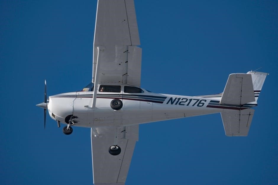
The Cessna 172 Service Manual is the definitive guide for maintaining this iconic aircraft, encompassing detailed procedures for all levels of technicians and owners․ This manual isn’t merely a collection of instructions; it’s a cornerstone of airworthiness, ensuring continued safe operation․ It meticulously outlines every aspect of the aircraft’s upkeep, from routine inspections to complex repairs, covering models Cessna 170, 170A, 170B, and the widely flown Cessna 172 series․

Crucially, this document must be readily available within the aircraft’s maintenance records; It serves as a reference point for adherence to regulatory standards and best practices․ Understanding its contents is paramount for anyone involved in the aircraft’s maintenance, guaranteeing compliance and promoting longevity․ The manual’s scope extends to engine specifics, airframe integrity, and system functionality․

Importance of the Aircraft Maintenance Manual (AMM)

The Aircraft Maintenance Manual (AMM) is fundamentally critical for the safe and continued airworthiness of any aircraft, especially the Cessna 172․ It’s not simply a helpful guide, but a legally mandated document ensuring all maintenance actions are performed to approved standards․ Proper adherence minimizes risks, extends the aircraft’s lifespan, and maintains its resale value․

Furthermore, the AMM provides a standardized approach to maintenance, reducing errors and promoting consistency across different maintenance facilities․ It details authorized modifications – known as minor change designs – and ensures proper documentation of all work performed in the aircraft’s logbooks․ Without a current and correctly utilized AMM, regulatory compliance becomes impossible, potentially grounding the aircraft and incurring significant penalties․

Document Control and Revision History

Maintaining strict document control is paramount with the Cessna 172 service manual․ The manual itself must be kept current, reflecting all applicable revisions and updates issued by Cessna or authorized aviation authorities․ A detailed revision history, typically found within the manual, tracks each change, including the date, reason, and specific pages affected․

This history is crucial for ensuring technicians are working with the most accurate information․ Outdated manuals can lead to incorrect maintenance procedures, potentially compromising safety․ Regular checks against official sources, like Cessna’s documentation, are essential․ Proper control also includes managing distribution – ensuring only authorized personnel have access to the current version, and that superseded copies are clearly marked and removed from service․

Aircraft Systems & Maintenance

Detailed procedures cover engine, airframe, landing gear, fuel, and electrical systems, ensuring proper Cessna 172 upkeep and operational reliability․

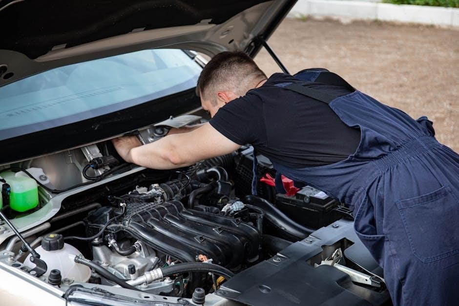
Engine Maintenance – Specific to Cessna 172 Models

Cessna 172 engine maintenance demands meticulous adherence to the service manual’s guidelines, varying slightly across models (F, G, H, I, K, L, M, N)․ Regular oil analysis is crucial, interpreting results to identify potential internal issues before they escalate․

Maintenance includes inspecting and replacing filters, checking magneto functionality, and ensuring proper carburetor operation․ Specific attention must be paid to TAE 125-02-114 engines, as outlined in IM-20-02S․

Motor oil changes should follow recommended schedules, utilizing appropriate grades․ Thorough inspection of cylinders, valves, and spark plugs is paramount․ Any discrepancies discovered during inspection require immediate attention and documentation within the aircraft’s logbook, adhering to approved maintenance releases․

Airframe Maintenance – Inspection and Repair

Comprehensive airframe maintenance, guided by the Cessna 172 service manual, is vital for structural integrity․ Inspections encompass the fuselage, wings, and tail surfaces, searching for corrosion, cracks, or damage․ Repair procedures must strictly adhere to approved data and minor change designs․

Regularly check control surfaces for freedom of movement and proper alignment․ Skin inspections are crucial, particularly around rivets and areas prone to stress․ Documentation of all inspections and repairs is mandatory in the aircraft’s maintenance logbook․

Any structural repairs require qualified personnel and approved materials․ Maintaining up-to-date flight and maintenance manuals ensures compliance with regulatory standards and safe operation․

Landing Gear Maintenance & Overhaul

Proper landing gear maintenance, as detailed in the Cessna 172 service manual, is paramount for safe landings and ground operations․ Inspections focus on shock struts, tires, brakes, and wheel assemblies, checking for wear, damage, and proper lubrication․

Overhaul schedules are dictated by time or cycles, requiring disassembly, inspection, and replacement of worn components․ Brake systems demand meticulous attention, ensuring effective stopping power․ Tire pressure and tread depth must be consistently monitored․

Detailed documentation of all landing gear work is essential for maintaining accurate maintenance records․ Adherence to the manual’s guidelines guarantees continued airworthiness and operational safety․

Fuel System Maintenance – Inspection and Cleaning

Maintaining a pristine fuel system, as outlined in the Cessna 172 service manual, is critical for engine performance and safety․ Regular inspections encompass fuel tanks, lines, filters, and the carburetor or fuel injection system, searching for leaks, corrosion, or obstructions․

Cleaning procedures involve draining fuel tanks to remove sediment and water, flushing fuel lines, and meticulously cleaning fuel filters․ Proper fuel grade and additive usage are also addressed․

Detailed logbook entries documenting all fuel system maintenance are crucial․ Strict adherence to the manual’s recommendations ensures reliable engine operation and prevents potential hazards․

Electrical System Maintenance – Troubleshooting and Repair

The Cessna 172’s electrical system demands diligent maintenance, as detailed within the service manual․ Troubleshooting procedures cover common issues like battery failures, faulty alternators, and wiring malfunctions․ The manual provides schematics for efficient fault isolation․

Repair procedures emphasize safe disconnection of power sources before working on any electrical component․ Replacement of damaged wiring, connectors, and circuit breakers is thoroughly explained․ Proper use of testing equipment, like multimeters, is essential․

Logbook documentation of all electrical repairs and inspections is paramount for maintaining airworthiness and ensuring continued safe operation of the aircraft’s systems․

Inspection Procedures

Detailed checklists within the Cessna 172 service manual guide annual, 100-hour, and pre-flight inspections, ensuring thorough examination of all aircraft components․

Annual Inspection Checklist

The annual inspection, a cornerstone of Cessna 172 maintenance, demands meticulous adherence to a comprehensive checklist detailed within the service manual․ This rigorous process, typically performed by a certified A&P mechanic, ensures continued airworthiness․ Key areas include a thorough examination of the engine – checking for wear, leaks, and proper operation – alongside a detailed inspection of the airframe for corrosion, cracks, and structural integrity․

Furthermore, the landing gear receives focused attention, encompassing inspection of tires, brakes, and the overall structural condition․ The fuel system is scrutinized for leaks and contamination, while the electrical system undergoes testing to verify proper functionality․ Control surfaces, cables, and the trim system are also carefully assessed․ Logbook documentation of all findings and corrective actions is paramount, ensuring a traceable maintenance history and compliance with regulatory requirements․

100-Hour Inspection Requirements

The 100-hour inspection, mandated for Cessna 172s operated for hire, represents a less extensive, yet crucial, maintenance check․ The service manual outlines specific requirements, focusing on items prone to wear or failure within this timeframe․ This includes a detailed inspection of the engine oil and filters, along with a check of propeller condition and security․

Additionally, the inspection covers flight controls, ensuring free and correct movement, and a review of the fuel system for leaks․ Landing gear tires and brakes receive attention, alongside a verification of the proper operation of all lights․ While not as exhaustive as the annual inspection, diligent completion and thorough documentation in the aircraft logbooks are essential for continued legal operation and maintaining airworthiness standards․

Pre-Flight Inspection Detailed Guide

The Cessna 172 service manual emphasizes a meticulous pre-flight inspection as paramount for safety․ This detailed guide begins with a walk-around, checking for structural damage, fuel leaks, and proper control surface movement; Tire pressure, brake functionality, and landing gear strut extension are critical components․

Next, the inspection moves to the engine compartment, verifying oil levels, coolant, and the security of engine accessories․ Inside the cockpit, instruments, flight controls, and avionics are thoroughly tested․ The pilot’s operating handbook (POH) supplements the service manual, providing specific checklists․ A comprehensive pre-flight, documented appropriately, mitigates risks and ensures a safe and enjoyable flight experience for all occupants․

Transponder and ELT Inspection Procedures

The Cessna 172 service manual details rigorous inspection procedures for the transponder and Emergency Locator Transmitter (ELT)․ Transponder functionality requires verifying proper code setting, altitude reporting, and response to interrogation from Air Traffic Control․ Regular testing, as mandated by regulations, confirms operational status․

ELT inspections involve checking battery expiration dates, antenna connection security, and performing self-tests to ensure signal transmission capability․ The manual stresses the importance of documenting these tests in the aircraft’s logbook․ Proper functioning of both systems is crucial for air traffic surveillance and search-and-rescue operations in emergency situations, contributing significantly to flight safety․

Component Maintenance

The Cessna 172 service manual guides detailed maintenance of avionics, trim, control cables, and flaps, ensuring optimal performance and airworthiness․

Avionics Maintenance – Troubleshooting Common Issues

Addressing avionics challenges within the Cessna 172 demands a systematic approach, detailed within the service manual․ Common issues include communication radio failures, navigation system inaccuracies, and transponder malfunctions․ The manual provides step-by-step troubleshooting guides, focusing on verifying power supply, antenna connections, and software integrity․

Proper diagnostics involve utilizing test equipment to isolate faults, referencing wiring diagrams, and consulting component maintenance manuals․ Regular inspections, as outlined, help prevent failures․ The manual emphasizes the importance of qualified technicians for complex repairs, ensuring adherence to FAA regulations and maintaining the aircraft’s safety and operational reliability․ Thorough logbook entries are crucial for tracking all avionics maintenance performed․

Trim System Maintenance – Rudder and Elevator

Maintaining the Cessna 172’s manually operated rudder and elevator trim is crucial for flight control․ The service manual details inspection procedures for proper operation, focusing on smooth movement and secure locking mechanisms․ Regular checks involve verifying cable tension, control surface travel, and the absence of binding or excessive play․

Lubrication of pivot points, as specified, prevents corrosion and ensures responsiveness․ The manual outlines adjustment procedures to correct imbalances or sluggish control feel․ Any worn or damaged components, including cables and linkages, must be replaced by qualified personnel․ Accurate logbook documentation of all maintenance is essential, guaranteeing continued airworthiness and pilot confidence during operation․

Control Cable Inspection and Replacement

The Cessna 172 service manual emphasizes rigorous control cable inspection as a cornerstone of airworthiness․ Inspections must cover the entire cable run – from cockpit controls to control surfaces – checking for fraying, kinking, corrosion, and proper tension․ Look closely at termination points for secure attachment and wear․

Replacement is mandatory if any defects are found, utilizing only Cessna-approved cables and hardware․ Proper routing is critical, adhering strictly to the manual’s diagrams to prevent interference or binding․ After replacement, a full range of motion test and control surface balance check are required․ Detailed logbook entries documenting cable serial numbers, dates, and personnel involved are essential for regulatory compliance and safety․

Flap System Maintenance – Actuation and Adjustment

The Cessna 172 service manual details meticulous flap system maintenance, focusing on smooth and precise actuation․ Inspections involve checking flap hinges for wear, proper movement throughout the range, and secure attachment of control linkages․ Examine the flap motor (if equipped) for proper operation and lubrication․

Adjustment is crucial for symmetrical flap deployment, verified using a flap position indicator or visual inspection․ Any binding or uneven movement requires immediate attention․ Replacement of worn components, like hinges or cables, must follow Cessna’s guidelines․ Thorough logbook documentation of all maintenance, adjustments, and component replacements is vital for continued airworthiness and regulatory adherence․

Troubleshooting & Repair

The Cessna 172 service manual guides technicians through diagnosing common issues, offering repair procedures, and interpreting oil analysis results for optimal performance․

Common Cessna 172 Maintenance Issues

Addressing typical Cessna 172 concerns requires diligent adherence to the service manual’s guidelines․ Frequent issues include carburetor icing, particularly during colder months, necessitating regular inspections and potential overhaul․ Oil leaks, often stemming from seals or gaskets, demand prompt attention to prevent engine damage․ Electrical system malfunctions, such as faulty wiring or failing components, are also common, requiring careful troubleshooting․

Furthermore, control cable wear and tear, alongside trim system inconsistencies, impact flight control and necessitate thorough inspection and potential replacement․ Landing gear maintenance, focusing on brake systems and tire condition, is crucial for safe landings․ The service manual provides detailed procedures for diagnosing and rectifying these issues, ensuring continued airworthiness and operational safety․ Proper logbook entries are vital for tracking all maintenance performed․

Oil Analysis Program & Interpretation

Implementing an oil analysis program is a proactive maintenance strategy detailed within the Cessna 172 service manual․ Regular oil samples reveal crucial insights into engine health, detecting wear metals like iron, aluminum, and copper․ Elevated levels indicate potential component degradation – piston rings, bearings, or cylinder walls․

Analyzing viscosity changes identifies fuel dilution or oil breakdown․ Spectrometric analysis pinpoints specific contaminants, such as coolant leaks or salt water intrusion․ The service manual provides acceptable limits for each parameter, aiding interpretation․ Trending data over time reveals wear patterns, allowing for preventative maintenance before catastrophic failure․ Accurate logbook documentation of oil analysis results is essential for tracking engine condition and maintaining airworthiness․

Minor Change Designs for Cessna 170/172 Series

The Cessna 172 service manual references numerous minor change designs applicable to the 170/172 series aircraft․ These designs, often documented as Maintenance Releases, authorize modifications enhancing safety or operational efficiency․ Examples include alterations to control systems, electrical components, or structural reinforcements․

Proper implementation requires strict adherence to the approved design documentation․ Mechanics must verify applicability to the specific aircraft serial number and ensure all associated inspections are completed․ Logbook entries must clearly detail the modification, including the design approval number and mechanic’s certification․ These changes are crucial for maintaining compliance with airworthiness directives and ensuring continued safe operation of the aircraft, as outlined within the manual․

Maintenance Release and Logbook Entries

The Cessna 172 service manual emphasizes meticulous record-keeping․ A Maintenance Release signifies completion of approved maintenance, authorizing the aircraft’s return to service․ This document details work performed, parts used (with serial numbers where applicable), and mechanic certification․

Corresponding Logbook Entries are paramount, mirroring the Maintenance Release details․ They provide a continuous history of the aircraft’s maintenance․ Mechanics must sign and date each entry, including their certificate number․ Proper logbook entries are vital for tracking compliance with inspection schedules, Airworthiness Directives, and minor change designs․ Accurate records are essential during audits and contribute to maintaining the aircraft’s airworthiness, as dictated by the manual’s procedures․

Regulatory Compliance & Programs

Adherence to regulations is key; the Cessna 172 manual supports Aircraft Maintenance Programs (AMPs), though LBA approval for ELA1 aircraft is evolving․

Aircraft Maintenance Program (AMP) Considerations

Developing a robust Aircraft Maintenance Program (AMP) for a Cessna 172 requires careful attention to regulatory guidelines and operational needs․ While the German LBA (Luftfahrt-Bundesamt) currently doesn’t approve AMPs for ELA1 aircraft – encompassing many Cessna 172s – operators must still maintain meticulous records and adhere to established inspection schedules․

Instead of a formal AMP, compliance relies on consistently updated flight and maintenance manuals․ This includes diligent tracking of all maintenance performed, utilizing the Cessna 172 service manual as the primary reference․ Operators should prioritize safety and airworthiness, ensuring all inspections and repairs are documented thoroughly in the aircraft’s logbooks․

Understanding the evolving regulatory landscape is crucial, as policies regarding AMPs for ELA1 aircraft may change․ Staying informed through official aviation authorities and industry resources is paramount for continued safe and compliant operation of the Cessna 172․

manual for shark professional vacuum

Shark Professional Vacuum: A Comprehensive Manual Guide

Welcome! This guide provides essential information for your Shark Professional vacuum, covering operation, maintenance, and safety—downloadable PDFs are readily available online.

Congratulations on selecting a Shark Professional vacuum! This manual is designed to ensure optimal performance and longevity of your cleaning companion. Your new vacuum boasts powerful suction and versatile features, including Lift-Away technology for reaching difficult areas.

Before first use, carefully review this guide to understand all functionalities and safety precautions. Accessing the official Shark manual online (via model number search) provides a comprehensive PDF resource. Familiarize yourself with components like the dust cup, filters, and attachments.

This guide will walk you through setup, operation in both upright and Lift-Away modes, and essential maintenance procedures. Proper care, including regular filter cleaning and brushroll maintenance, will maximize cleaning efficiency and extend the life of your Shark vacuum.

Understanding Your Model Number (NV501, IZ400, etc.)

Identifying your specific Shark Professional vacuum model is crucial for accessing the correct manual and support resources. Common model numbers include NV501, IZ400, and variations within the Navigator and Stratos series. This number is typically located on a sticker on the underside of the vacuum unit or within the dust cup compartment.

The model number dictates the specific features, accessories, and filter types compatible with your vacuum. When downloading the official manual from the Shark website, always input the complete model number to ensure accuracy.

Incorrect manual usage can lead to improper maintenance or operation. Knowing your model allows you to find targeted troubleshooting advice and warranty information specific to your Shark vacuum.

Key Features and Components

Shark Professional vacuums boast Lift-Away technology, powerful suction, and versatile attachments for comprehensive cleaning on floors and above—explore each component!

Upright Mode Operation

Utilizing your Shark in upright mode is straightforward for standard floor cleaning. Ensure the dust cup is securely attached and the filters are correctly installed for optimal performance. Power on the vacuum and adjust the brushroll settings based on your floor type – carpet or hard floor.

The brushroll switch allows you to turn the brushroll on or off. For delicate hard floors, disengage the brushroll to prevent scratching. For carpets, engage the brushroll for deep cleaning and effective dirt removal. Maneuver the vacuum with smooth, overlapping strokes, allowing the powerful suction to lift debris.

Remember to maintain a consistent pace for best results. The swivel steering facilitates easy navigation around furniture and obstacles. Regularly check the brushroll for tangled hair or debris to maintain suction power.

Lift-Away Mode: Detaching and Using the Canister

The Lift-Away feature provides versatile cleaning for above-floor surfaces and hard-to-reach areas. To detach the canister, locate the release button – typically on the handle or pod – and press to unlock. Carefully lift the canister away from the base, ensuring it’s securely held.

Attach the desired accessory – crevice tool, dusting brush, or upholstery tool – to the canister’s wand. This allows targeted cleaning of furniture, stairs, and tight spaces. The lightweight canister is easy to carry and maneuver.

Remember to reattach the canister to the base for upright vacuuming. Ensure a firm click confirms secure connection.

Power Cord and Electrical Safety

Always prioritize electrical safety when operating your Shark Professional vacuum. Never pull the vacuum by the cord; grasp the plug directly to disconnect it from the outlet. Avoid using extension cords, as they can pose a tripping hazard and may not be compatible with the vacuum’s power requirements.

Inspect the cord regularly for damage – cuts, fraying, or exposed wires. Do not use the vacuum if the cord is damaged. Contact Shark customer support for repair or replacement. Keep the cord away from heated surfaces and avoid running it under rugs or furniture.

Ensure the outlet is properly grounded and avoid using the vacuum in wet or damp environments.

Dust Cup: Emptying and Cleaning

Regularly emptying the dust cup is crucial for maintaining optimal suction power. Detach the dust cup from the vacuum pod by following the release mechanism – typically a button or latch. Empty the contents into a trash receptacle, avoiding overfilling.

For thorough cleaning, wash the dust cup with cool water and a mild detergent. Ensure it is completely dry before reattaching it to the vacuum. Check for any blockages in the dust cup opening or within the canister itself.

Periodically wipe down the exterior of the dust cup with a damp cloth. Do not use abrasive cleaners or solvents.

Filtration System

Shark’s advanced filtration utilizes pre-motor and HEPA filters, capturing dust and allergens for a cleaner home environment—regular maintenance is key!

Filter Types: Pre-Motor and HEPA

Understanding your Shark’s filtration system is crucial for optimal performance. The pre-motor filter, typically foam or felt, protects the motor from large debris, extending its lifespan. It’s washable and should be cleaned regularly – usually monthly – to maintain suction power.

The HEPA filter (High-Efficiency Particulate Air) is your vacuum’s final defense, trapping 99.97% of microscopic particles like dust mites, pollen, and pet dander. This is especially important for allergy sufferers.

HEPA filters are not washable and require periodic replacement, typically every 6-12 months, depending on usage. Using non-Shark filters can void your warranty and compromise air quality, so always use genuine replacements. Check your model’s manual for specific filter types and replacement schedules.

Cleaning and Replacing Filters

Maintaining clean filters is vital for consistent suction. The pre-motor filter, after removal, should be hand-washed with cool water, ensuring it’s completely dry – typically 24 hours – before reinstallation. Avoid using detergents or soap.

HEPA filters cannot be washed. To replace, locate the filter compartment (refer to your model’s manual). Remove the old filter and insert the new one, ensuring a secure fit.

Regular inspection is key; a dirty or damaged filter significantly reduces cleaning effectiveness. Replacement frequency depends on usage, but generally, pre-motor filters need monthly cleaning and HEPA filters should be replaced every 6-12 months. Always unplug the vacuum before filter maintenance.

Importance of Filter Maintenance

Consistent filter maintenance directly impacts your Shark vacuum’s performance and longevity. Dirty filters restrict airflow, causing a loss of suction and forcing the motor to work harder, potentially leading to overheating and reduced lifespan.

Furthermore, compromised filtration allows fine dust and allergens to recirculate into the air, diminishing air quality. Regularly cleaning or replacing filters ensures optimal suction power, efficient cleaning, and a healthier home environment.

Neglecting filter care voids the warranty and can necessitate costly repairs. Prioritize filter upkeep for a powerful, reliable, and hygienic vacuuming experience.

Accessories and Attachments

Enhance cleaning versatility with included tools like the crevice tool, dusting brush, upholstery tool, and the powerful Pet Power Brush for targeted cleaning.

Crevice Tool: For Tight Spaces

The crevice tool is specifically designed to access narrow and hard-to-reach areas where standard vacuum heads cannot fit effectively. This attachment excels at cleaning along edges, in corners, between furniture cushions, and within tight gaps.

To utilize the crevice tool, securely attach it to the vacuum wand or directly to the Lift-Away canister. Apply gentle pressure while maneuvering the tool along the desired surface. Its slender profile allows for precise cleaning, removing dust, dirt, and debris from these often-neglected spaces.

Regular use of the crevice tool contributes to a more thorough and comprehensive cleaning experience, ensuring no area is left untouched. It’s an invaluable asset for maintaining a spotless home environment.

Dusting Brush: For Delicate Surfaces

The dusting brush attachment is ideal for gently cleaning delicate surfaces that could be scratched or damaged by harsher vacuum tools. This includes furniture, lampshades, bookshelves, and decorative items. Its soft bristles effectively lift dust without causing abrasion.

Attach the dusting brush to the vacuum wand or Lift-Away canister for extended reach. Use a light touch and slow, sweeping motions to avoid disturbing items or applying excessive pressure. The brush’s design allows it to conform to contours and capture dust from intricate details.

Regular dusting with this attachment preserves the appearance and condition of your valuable belongings, preventing dust buildup and maintaining a pristine home.

Upholstery Tool: Cleaning Furniture

The upholstery tool is specifically designed for effective cleaning of furniture, including sofas, chairs, and ottomans. It gently lifts dirt, dust, and pet dander from fabric surfaces without causing damage. This attachment is crucial for maintaining a clean and healthy living space.

Attach the upholstery tool to the vacuum wand or Lift-Away canister. Test on an inconspicuous area first to ensure compatibility with the fabric. Use overlapping strokes, applying gentle pressure to agitate and remove embedded debris.

For optimal results, regularly vacuum upholstery to prevent dust and allergens from accumulating. This tool helps extend the life of your furniture and improves indoor air quality.

Pet Power Brush: Removing Pet Hair

The Pet Power Brush is a specialized attachment engineered to tackle stubborn pet hair on upholstery, carpets, and stairs. Its rotating brushroll effectively lifts and removes embedded hair, dander, and allergens, leaving surfaces thoroughly clean. This tool is indispensable for pet owners seeking a hair-free home.

Securely attach the Pet Power Brush to the vacuum wand or Lift-Away canister. Activate the brushroll and use short, overlapping strokes across the affected areas. For carpets, adjust the brushroll height as needed for optimal performance.

Regular use of the Pet Power Brush minimizes pet hair buildup and contributes to a healthier indoor environment. Consistent cleaning prevents allergens from circulating and improves air quality.

Maintenance and Troubleshooting

Keep your Shark running smoothly! Regularly clean the brushroll, check for blockages, and address issues like suction loss or overheating for peak performance.

Brushroll Cleaning: Removing Hair and Debris

Maintaining a clean brushroll is crucial for optimal suction and cleaning performance with your Shark Professional vacuum. Regularly inspect the brushroll for tangled hair, string, and debris. Always unplug the vacuum before attempting any maintenance! Carefully remove the brushroll cover, typically by releasing clips or screws.

Once accessible, use scissors or the provided cleaning tool (if included with your model) to carefully cut and remove any wrapped materials. Ensure all debris is cleared from the bristles. Reinstall the brushroll, securing the cover properly; A clogged brushroll significantly reduces cleaning effectiveness and can strain the motor. Consistent cleaning extends the life of your vacuum and ensures powerful performance on all floor types. Refer to your specific model’s manual for detailed instructions and diagrams.

Checking for Blockages in Hoses and Ducts

Loss of suction often indicates a blockage within the hose, wand, or ducts of your Shark Professional vacuum. Always disconnect the power before inspecting for obstructions. Detach the hose and wand, visually inspecting for visible clogs. Use a long, flexible object – like a broom handle – to gently dislodge any blockages.

Check the floor nozzle and the area where the hose connects to the vacuum body. Ensure the dust cup is empty, as a full cup can restrict airflow. A thorough inspection prevents motor overheating and maintains optimal cleaning power. Refer to your model’s manual for specific disassembly instructions. Regular checks and prompt removal of blockages are vital for sustained performance.

Troubleshooting Common Issues (Loss of Suction, Overheating)

Loss of suction is frequently caused by a full dust cup, clogged filters, or blockages in hoses and ducts. Overheating typically results from restricted airflow due to these same issues. First, empty the dust cup and clean or replace the filters. Inspect the hose, wand, and floor nozzle for obstructions, removing any debris found.

If overheating persists, immediately turn off and unplug the vacuum, allowing it to cool completely. Avoid using the vacuum on excessively thick carpets for extended periods. Consult your model’s manual for specific troubleshooting steps and error indicators. Contact Shark customer support if problems continue.

Safety Precautions

Always unplug before servicing, never use with wet hands, and do not operate without filters—use only Shark accessories for safe operation.

Avoiding Damage to the Vacuum

Protect your investment! To prevent damage, never operate the Shark vacuum with a full dust cup, as this can strain the motor and reduce suction power. Avoid vacuuming large, hard objects or sharp items that could harm the brushroll or internal components.

Regularly check for blockages in the hose, wand, and floor nozzle, as obstructions can cause overheating and motor failure. Do not pull the vacuum by the cord; always grasp the plug to disconnect it. Ensure the filters are clean and properly installed, as a clogged filter restricts airflow and can damage the motor. Avoid using the vacuum on excessively wet surfaces, and always follow the floor type guidelines to prevent scratching or damage.

Proper Usage on Different Floor Types

Optimize cleaning! For hard floors, switch off the brushroll to prevent scattering debris and avoid scratching. Utilize the bare floor setting if available; On carpets, engage the brushroll for effective dirt removal; adjust the height setting for optimal performance based on carpet pile.

Delicate rugs require a gentle approach – use the lowest suction setting or the handheld mode. Avoid using the motorized brush head on delicate area rugs. Always test a small, inconspicuous area first. Do not force the vacuum across transitions between floor types; adjust settings accordingly. Regular adjustments ensure efficient cleaning and prolong the life of your Shark vacuum.

Electrical Safety Guidelines

Prioritize safety! Always unplug the vacuum before any maintenance or troubleshooting. Never operate with a damaged cord or plug – replace immediately. Do not use outdoors or on wet surfaces. Avoid pulling the cord to unplug; grasp the plug itself.

Ensure the electrical outlet is properly grounded. Do not use an extension cord unless absolutely necessary, and if so, select one rated for the vacuum’s amperage. Keep the cord away from heated surfaces and sharp objects. Never attempt to repair the vacuum yourself; contact qualified service personnel. Following these guidelines prevents electrical hazards and ensures safe operation.

Downloading the Official Shark Manual

Access digital copies! Easily find your Shark vacuum’s manual online by entering your specific model number for a downloadable PDF version.

Locating Your Model’s Manual Online

Finding your specific Shark Professional vacuum manual is straightforward! Begin by visiting the official Shark website. Navigate to the support section, often labeled “Customer Support” or “Manuals & FAQs.”

There, you’ll typically find a search bar or a dedicated manual lookup tool. Enter your vacuum’s model number – crucial for accurate results (e.g., NV501, IZ400). The website will then display a list of relevant manuals.

Alternatively, a broader search using keywords like “Shark vacuum manual” plus your model number in a search engine (Google, Bing) can also lead you directly to the official PDF. Ensure the website is legitimate to avoid downloading potentially harmful files. Shark’s official site guarantees a safe and accurate download.

PDF Manual Access and Features

Downloaded Shark Professional vacuum manuals are typically in PDF format, offering convenient access and usability. These digital manuals are searchable, allowing you to quickly find specific information regarding troubleshooting, maintenance, or operation.

PDFs often include detailed diagrams illustrating component locations and assembly instructions. You can zoom in for clarity and print specific pages for easy reference during cleaning or repairs.

Features commonly found within the PDF include safety precautions, a comprehensive parts list, step-by-step instructions for various tasks, and warranty information. Digital access ensures you always have the latest version of your manual readily available, eliminating the need for physical storage.

Warranty Information

Shark vacuums come with a limited warranty covering defects in materials and workmanship; review your manual for specific terms and customer support details.

Understanding Your Shark Warranty

Your Shark Professional vacuum is protected by a limited warranty, designed to ensure your satisfaction and peace of mind. The duration and coverage specifics vary depending on your exact model – always refer to the warranty information included with your vacuum or available in the official manual.

Generally, the warranty covers defects in materials and workmanship under normal household use. It does not cover damage resulting from misuse, accidents, alterations, or lack of proper maintenance, like filter cleaning. Proof of purchase is crucial for any warranty claim.

To initiate a claim, contact Shark Customer Support (details provided later). Be prepared to provide your model number, purchase date, and a description of the issue. Retain your original packaging, as it may be required for returns. Understanding these terms will streamline any potential warranty process.

Contacting Shark Customer Support

Need assistance with your Shark Professional vacuum? Shark offers multiple channels for customer support, ensuring you can easily find solutions to your questions or concerns. The quickest way to get help is often through their official website, where you’ll find a comprehensive FAQ section and troubleshooting guides.

For direct assistance, you can reach Shark via their toll-free number: 1-800-798-7398. Be prepared to have your model number handy. Alternatively, explore their website for live chat options or email support.

Remember to have your purchase information available when contacting support. Shark’s customer service team is dedicated to providing prompt and helpful assistance, ensuring your vacuum operates optimally.

church of god in christ official manual

Article Plan: Church of God in Christ Official Manual

This manual details the COGIC’s history‚ beliefs‚ structure‚ and practices‚ encompassing worship‚ discipline‚ education‚ and outreach to its global community of believers.

I. Historical Foundations of the COGIC

The Church of God in Christ (COGIC) emerged from the fervent Pentecostal movement of the early 20th century‚ rooted in the Holiness tradition. Its origins trace back to 1897 in Lexington‚ Mississippi‚ with Charles H. Mason and Charles P. Appling establishing the initial Christian faith-based organization.

Early gatherings focused on spiritual experiences‚ including speaking in tongues and divine healing‚ differentiating it from established denominations. In 1907‚ the organization formally adopted the name “Church of God in Christ‚” solidifying its identity. The COGIC rapidly grew‚ particularly within African American communities‚ offering spiritual empowerment and a sense of belonging during a period of significant social and racial challenges.

This growth was fueled by missionary work and the establishment of numerous local churches across the United States and‚ eventually‚ internationally. The historical foundations of COGIC are deeply intertwined with the pursuit of religious freedom and the empowerment of a marginalized community.

II. Doctrinal Beliefs – Core Tenets

COGIC’s doctrinal foundation centers on the belief in one God‚ manifested in the Trinity: Father‚ Son (Jesus Christ)‚ and Holy Spirit. Central to their faith is the full divinity of Jesus Christ‚ His atoning sacrifice for humanity’s sins‚ and His resurrection.

The Pentecostal experience‚ including baptism in the Holy Spirit evidenced by speaking in tongues‚ is considered essential for Christian living. COGIC affirms the Bible as the inspired and infallible Word of God‚ the ultimate authority for faith and practice.

Key tenets include salvation through faith in Jesus Christ‚ water baptism by immersion‚ and the observance of the Holy Communion. They believe in divine healing‚ the imminent return of Christ‚ and the importance of holy living‚ striving for sanctification and a life pleasing to God. These beliefs shape the COGIC’s worship and daily life.

III. Organizational Structure of the COGIC

The Church of God in Christ operates under a hierarchical structure‚ emphasizing both national unity and local autonomy. At the apex is the General Assembly‚ convened every two years‚ comprising bishops and key leaders who establish church-wide policies and address critical issues.

Below the General Assembly are various departments overseeing specific ministries like evangelism‚ education‚ and women’s work. The organizational framework extends down through districts‚ each led by a district superintendent‚ and ultimately to individual local churches governed by their pastors and boards.

This structure facilitates coordinated efforts in missions‚ education‚ and outreach while allowing local churches to adapt to their community’s unique needs. Accountability and adherence to COGIC doctrine are maintained throughout all levels of the organization‚ ensuring consistent standards and effective ministry.

III.A. National Church Leadership

COGIC’s national leadership is vested in the General Assembly‚ a body of bishops representing districts across the globe. The Presiding Bishop‚ elected by the Assembly‚ serves as the spiritual and administrative head‚ guiding the church’s overall direction and representing it nationally and internationally.

Assisting the Presiding Bishop are Assistant Presiding Bishops‚ who oversee specific departments and initiatives. The General Secretary manages administrative functions‚ while other key leaders direct departments focused on areas like finance‚ education‚ and evangelism.

These leaders collectively establish policies‚ resolve disputes‚ and ensure the church operates in accordance with its doctrinal beliefs and constitutional guidelines‚ fostering unity and effective ministry across the denomination.

III.B. District and Local Church Governance

COGIC’s district structure operates under the authority of the National Church Leadership‚ with each district overseen by a District Superintendent appointed by the Presiding Bishop. The Superintendent provides guidance‚ support‚ and accountability to the local churches within their assigned district.

Local churches are governed by a Pastor and a Board of Elders‚ responsible for spiritual leadership‚ administrative oversight‚ and financial management. Deacons assist with ministry and service‚ while various auxiliaries support specific areas like evangelism‚ missions‚ and Christian education.

This tiered governance system ensures both centralized guidance and local autonomy‚ allowing each church to address the unique needs of its community while remaining aligned with the broader COGIC vision and doctrine.

IV. Ordination Procedures and Requirements

COGIC’s ordination process is rigorous‚ ensuring candidates meet stringent biblical and denominational standards. Aspiring ministers must first obtain a license‚ demonstrating a call to ministry and foundational theological understanding.

Following licensure‚ candidates undergo extensive training‚ including coursework in biblical studies‚ homiletics‚ and pastoral care. They are evaluated on character‚ spiritual maturity‚ and demonstrated ministry effectiveness within the local church.

Ordination requires endorsement from the local pastor‚ district superintendent‚ and ultimately‚ the National Board of Bishops. Successful candidates are then ordained as Elders‚ Ministers‚ or Bishops‚ depending on their qualifications and calling‚ signifying their commitment to lifelong service.

V. Sacraments and Ordinances – COGIC Practice

COGIC observes sacraments and ordinances as sacred acts symbolizing spiritual realities and obedience to Christ’s commands. Baptism‚ typically by full immersion‚ signifies the believer’s death to sin and resurrection to new life in Christ‚ a public declaration of faith.

Holy Communion‚ or the Lord’s Supper‚ is observed regularly‚ commemorating Christ’s sacrifice and fostering fellowship among believers. It’s a solemn occasion of remembrance and spiritual nourishment.

Foot washing‚ a unique COGIC practice‚ embodies humility and service‚ mirroring Christ’s example of washing the disciples’ feet. These ordinances are central to COGIC worship and spiritual growth.

V.A. Baptism – Modes and Significance

COGIC adheres to baptism by immersion as the only scripturally valid mode‚ symbolizing death‚ burial‚ and resurrection with Christ. This public declaration signifies a believer’s commitment to follow Christ and separation from a former life.

Baptism isn’t merely an outward rite but an inward transformation‚ representing cleansing from sin and entering into a new covenant relationship with God. It’s a vital step of obedience following salvation.

Infant baptism is not practiced‚ as COGIC believes baptism requires a conscious profession of faith. The act demonstrates identification with Christ’s death and a commitment to live a life pleasing to God.

V.B. Holy Communion – Observance and Meaning

COGIC observes Holy Communion‚ also known as the Lord’s Supper‚ as a sacred ordinance instituted by Jesus Christ during His last Passover meal with disciples. It’s a memorial feast‚ commemorating Christ’s sacrifice on the cross for the remission of sins.

The observance typically involves unleavened bread representing Christ’s body‚ broken for us‚ and grape juice symbolizing His blood‚ shed for our redemption. Participation is reserved for those who are baptized believers in good standing.

Communion isn’t simply a ritual; it’s a profound spiritual experience fostering fellowship with Christ and fellow believers‚ prompting self-examination and renewed commitment to discipleship.

VI. Worship Services – Liturgical Guidelines

COGIC worship services are vibrant‚ expressive‚ and deeply rooted in tradition‚ emphasizing both reverence and enthusiastic praise. Services typically begin with praise and worship‚ often featuring spirited music led by choirs‚ musicians‚ and praise teams.

The order of service generally includes prayer‚ scripture reading‚ a sermon delivered by the pastor‚ and opportunities for testimonies and announcements. A significant element is the “shouting” tradition‚ an outward expression of joy and spiritual fervor.

COGIC services prioritize the preaching of the Gospel and the pursuit of a genuine encounter with the Holy Spirit‚ aiming to create an atmosphere conducive to spiritual transformation and renewal.

VII. Church Discipline – Biblical Principles

COGIC’s approach to church discipline is firmly grounded in biblical principles‚ prioritizing restoration and reconciliation while upholding moral standards. Discipline aims to address sin within the congregation‚ encouraging repentance and preventing further spiritual harm.

The process typically involves private counsel with the offender‚ followed by involvement of church leadership if repentance isn’t forthcoming. Public rebuke may occur‚ guided by Matthew 18 principles‚ always seeking to avoid shaming but maintain accountability.

Exclusion from communion or membership are considered last resorts‚ employed only after diligent efforts at restoration have failed. Forgiveness and reintegration are central goals‚ reflecting God’s grace and mercy.

VIII. Missions and Evangelism – COGIC Outreach

COGIC’s commitment to missions and evangelism stems from the Great Commission‚ actively seeking to spread the Gospel globally. Outreach efforts encompass both domestic and international initiatives‚ establishing new churches and supporting existing ministries.

The church emphasizes holistic ministry‚ addressing spiritual and physical needs through various outreach programs. These include providing aid to impoverished communities‚ disaster relief‚ and educational opportunities.

COGIC missionaries are deployed worldwide‚ often working in challenging environments‚ demonstrating unwavering faith and dedication. Evangelistic crusades‚ bible distribution‚ and community engagement are key strategies employed to reach unreached populations‚ fulfilling its divine calling.

IX. Christian Education – Curriculum and Programs

COGIC prioritizes comprehensive Christian education‚ fostering spiritual growth and intellectual development across all age groups. The curriculum is biblically centered‚ emphasizing doctrine‚ discipleship‚ and practical application of faith principles.

Programs range from early childhood education to adult learning‚ equipping members with the knowledge and skills to serve effectively in ministry and society. Sunday School serves as a foundational element‚ providing age-appropriate biblical instruction.

Bible study resources‚ leadership training‚ and theological education are also integral components‚ preparing individuals for various roles within the church and beyond. COGIC aims to cultivate informed‚ engaged‚ and devoted followers of Christ.

IX.A. Sunday School – Structure and Objectives

COGIC’s Sunday School is structured to provide age-graded biblical instruction‚ fostering a lifelong love for learning God’s Word. Classes are organized by age groups – Beginners‚ Primary‚ Intermediate‚ and Youth/Adult – each with tailored lessons and teaching methods.

The primary objective is to lead individuals to a saving knowledge of Jesus Christ and nurture their spiritual growth through consistent Bible study. Sunday School aims to equip members with a foundational understanding of biblical doctrines and principles.

Furthermore‚ it encourages active participation in church life and prepares individuals for effective Christian service. Qualified teachers‚ engaging materials‚ and a supportive learning environment are crucial components of COGIC’s Sunday School program.

IX.B; Bible Study – Methods and Resources

COGIC promotes diverse Bible study methods to cater to varied learning styles‚ including inductive study‚ topical studies‚ and character studies. These methods encourage active engagement with scripture‚ moving beyond mere reading to thoughtful interpretation and application.

Resources utilized include approved COGIC curriculum‚ commentaries‚ Bible dictionaries‚ concordances‚ and digital Bible study tools. Emphasis is placed on contextual understanding‚ considering historical and cultural backgrounds.

Small group Bible studies are highly encouraged‚ fostering fellowship and accountability. Leaders are trained to facilitate discussions‚ answer questions‚ and guide participants in applying biblical truths to their lives. The goal is to cultivate a deeper relationship with God through consistent‚ informed Bible study.

X. Financial Administration – Stewardship and Accountability

COGIC emphasizes financial stewardship as a sacred responsibility‚ reflecting biblical principles of tithing‚ offerings‚ and responsible resource management. All financial practices must adhere to strict accountability standards‚ ensuring transparency and integrity.

The manual outlines procedures for budgeting‚ record-keeping‚ and financial reporting at all levels – local‚ district‚ and national. Designated financial officers receive training in proper accounting procedures and internal controls.

Regular audits are conducted to verify financial accuracy and compliance. Funds are allocated to support ministry initiatives‚ missions‚ and operational expenses‚ always prioritizing the advancement of God’s kingdom. Faithful giving is presented as an act of worship and trust in divine provision.

XI. Pastoral Responsibilities and Ethics

This section defines the multifaceted role of COGIC pastors‚ emphasizing spiritual leadership‚ biblical teaching‚ and compassionate shepherding of the flock. Pastors are called to exemplify Christ-like character‚ maintaining a high standard of ethical conduct in all aspects of life.

The manual details responsibilities including preaching‚ counseling‚ administering sacraments‚ and providing pastoral care. It addresses ethical considerations regarding financial dealings‚ relationships‚ and conflict resolution.

Pastors are accountable to church leadership and expected to adhere to a strict code of conduct. Ongoing professional development and mentorship are encouraged to enhance their effectiveness. Emphasis is placed on integrity‚ humility‚ and a commitment to lifelong learning.

XII; Women’s Department – Roles and Ministries

This section outlines the significant contributions of women within the Church of God in Christ‚ recognizing their vital roles in ministry and leadership. The COGIC Women’s Department fosters spiritual growth‚ provides supportive networks‚ and empowers women to fulfill their God-given potential.

Ministries encompass areas like evangelism‚ discipleship‚ missions‚ and community outreach. The manual details opportunities for women to serve in various capacities‚ utilizing their unique gifts and talents.

Emphasis is placed on biblical womanhood‚ promoting values of faith‚ family‚ and service. Leadership development programs are available to equip women for effective ministry. The department actively supports initiatives addressing the needs of women and families within the church and broader community.

XIII. Youth and Young Adult Ministries – Development and Engagement

This section details the COGIC’s commitment to nurturing the spiritual development of its youth and young adults‚ recognizing them as the future leaders of the church. The manual outlines strategies for engaging this demographic through relevant and impactful ministries.

Programs focus on biblical instruction‚ discipleship‚ leadership training‚ and mentorship opportunities. Emphasis is placed on fostering a strong sense of community and providing a safe space for exploration of faith.

The COGIC encourages youth involvement in evangelism‚ missions‚ and social justice initiatives. Resources are provided to support youth leaders and parents in guiding young people through the challenges of adolescence and young adulthood‚ equipping them to live purposeful lives for Christ.

XIV. Music and Worship – COGIC Tradition

This section explores the rich musical heritage and worship traditions deeply ingrained within the Church of God in Christ. COGIC’s worship style is characterized by passionate expression‚ fervent prayer‚ and dynamic music‚ reflecting its African American roots.

The manual details the significance of gospel music‚ including traditional hymns‚ contemporary praise and worship‚ and the distinctive use of instruments like the organ‚ piano‚ and drums. Emphasis is placed on creating an atmosphere conducive to spiritual encounter and heartfelt adoration.

Guidelines are provided for worship leadership‚ ensuring reverence‚ order‚ and inclusivity. COGIC believes music is a powerful tool for evangelism‚ edification‚ and glorifying God‚ fostering a vibrant and transformative worship experience.

XV. Dispute Resolution – COGIC Protocols

This section outlines the established procedures for addressing conflicts and resolving disputes within the Church of God in Christ‚ prioritizing biblical principles and reconciliation. The manual emphasizes a restorative approach‚ seeking to mend relationships and maintain unity among members.

COGIC’s dispute resolution process begins with informal mediation‚ encouraging direct communication and mutual understanding. If unresolved‚ the matter escalates through a defined hierarchy – local church leadership‚ district officials‚ and ultimately‚ the national church body.

Detailed guidelines are provided for conducting investigations‚ gathering evidence‚ and ensuring fairness. The goal is to achieve just and equitable outcomes‚ upholding the integrity of the church and fostering a harmonious community based on love and respect.

piper cherokee service manual

The Piper Cherokee Service Manual is a comprehensive guide for maintaining PA-28 series aircraft, covering inspections, repairs, and compliance with aviation standards for safe operation.

1.1 Overview of the Piper Cherokee Aircraft Series

The Piper Cherokee series includes models PA-28-140, PA-28-150, PA-28-160, PA-28-180, PA-28-235, PA-28R-180, and PA-28R-200. These single-engine, four-seat aircraft are known for their reliability and versatility, suitable for training, recreation, and light transportation. The series offers varying engine power and configurations, catering to different pilot needs and preferences. This overview provides a foundation for understanding the aircraft’s design and operational capabilities, essential for effective maintenance and flight operations.

1.2 Purpose and Scope of the Service Manual

The Piper Cherokee Service Manual provides detailed instructions for maintaining and repairing PA-28 series aircraft. It covers routine inspections, scheduled maintenance, and compliance with aviation standards. The manual is designed for mechanics and owners to ensure continued airworthiness. It includes troubleshooting, repair procedures, and guidelines for handling hazardous materials. The scope encompasses all models, offering a comprehensive resource for safe and efficient aircraft operation and maintenance.

Models Covered in the Service Manual

The Piper Cherokee Service Manual covers models PA-28-140, PA-28-150, PA-28-160, PA-28-180, PA-28-235, PA-28R-180, and PA-28R-200, providing essential information for each to ensure compliance and optimal performance.

2.1 PA-28-140 Cherokee

The PA-28-140 Cherokee is a popular single-engine aircraft covered in the service manual, part number 753-586. It provides detailed instructions for inspections, maintenance, and repairs specific to this model. The manual includes guidelines for routine checks, scheduled maintenance tasks, and compliance with aviation standards. It is an essential resource for owners, mechanics, and pilots to ensure the aircraft remains airworthy and operates safely. Regular adherence to the manual’s procedures is crucial for optimal performance and longevity.

2.2 PA-28-150 Cherokee

The PA-28-150 Cherokee, part of the service manual (P/N 753-586), is a single-engine aircraft with a 150-hp engine. The manual provides detailed maintenance procedures, including inspections, repairs, and compliance with aviation standards. It covers routine tasks, scheduled maintenance, and airworthiness requirements. This model’s performance and durability make it a popular choice, and the manual ensures owners and mechanics can maintain it effectively for safe and reliable operation.

2.3 PA-28-160 Cherokee

The PA-28-160 Cherokee, covered in the service manual (P/N 753-586), features a 160-hp engine, offering enhanced performance. The manual details maintenance procedures, including inspections, repairs, and compliance with aviation standards. It ensures owners and mechanics can perform routine tasks and scheduled maintenance effectively, supporting the aircraft’s reliability and safety. This model’s capabilities make it a preferred choice, with the manual being an essential resource for its upkeep.

2.4 PA-28-180 Cherokee

The PA-28-180 Cherokee, covered in the service manual (P/N 753-586), is a popular model with a 180-hp engine, offering improved performance and versatility. The manual provides detailed maintenance procedures, including inspections, repairs, and compliance guidelines. It ensures owners and mechanics can maintain the aircraft’s airworthiness, addressing specific features of the PA-28-180. This model’s robust design and reliability make it a favorite, with the manual serving as an indispensable resource for its upkeep and safety.

2.5 PA-28-235 Cherokee

The PA-28-235 Cherokee, detailed in the service manual (P/N 753-586), features a powerful 235-hp engine, enhancing performance and payload capacity. The manual outlines specific maintenance requirements, including engine care and airframe inspections. Its robust design and higher power output make it suitable for demanding operations. The service manual ensures compliance with aviation standards, providing clear guidelines for inspections, repairs, and ongoing airworthiness, tailored to this model’s unique characteristics and operational needs.

2.6 PA-28R-180 Cherokee

The PA-28R-180 Cherokee, covered in the service manual (P/N 753-586), is a retractable-gear variant with a 180-hp engine, offering improved performance and efficiency. The manual provides detailed maintenance procedures, including gear system inspections and engine specifications. Its design enhances aerodynamic performance, making it suitable for both training and personal use. The service manual ensures adherence to aviation standards, with specific guidelines for inspections, repairs, and ongoing airworthiness for this model.

2.7 PA-28R-200 Cherokee

The PA-28R-200 Cherokee, covered in the service manual (P/N 753-586), features a 200-hp engine and retractable landing gear, offering enhanced performance and efficiency. The manual provides detailed maintenance procedures, including gear system inspections and engine specifications. Designed for improved aerodynamic performance, this model is ideal for both training and personal use. The service manual ensures compliance with aviation standards, with specific guidelines for inspections, repairs, and ongoing airworthiness for this variant.

Structure and Organization of the Service Manual

The service manual is organized into sections, including an index guide and revision status, ensuring easy access to maintenance procedures and updates for all Cherokee models.

3.1 Section Index Guide

3.2 Revision Status and Updates

The Piper Cherokee Service Manual’s revision status and updates are meticulously tracked to ensure compliance with aviation standards. Revisions are detailed in the manual, with part number 753-586, last updated on January 31, 2008. Updates are incorporated through Aerofiche cards, ensuring all maintenance procedures remain current and accurate. Users are advised to consult the Customer Service Information Aerofiche for the most recent revision dates and changes, ensuring all maintenance procedures remain current and accurate for safe operations.

Maintenance Schedules and Procedures

The manual outlines routine inspections and scheduled maintenance tasks to ensure compliance with aviation standards, promoting aircraft safety and longevity through systematic upkeep procedures.

4.1 Routine Inspections and Checks

The Piper Cherokee Service Manual details routine inspections and checks to ensure aircraft airworthiness. These include pre-flight, post-flight, and periodic inspections of critical systems and components. Regular checks cover control surfaces, landing gear, tires, brakes, and fluid levels. Additionally, the manual specifies inspection intervals for engine components, propellers, and avionics to maintain safety and performance. Adhering to these procedures ensures compliance with aviation standards and prolongs aircraft lifespan.

4.2 Scheduled Maintenance Tasks

The Piper Cherokee Service Manual outlines scheduled maintenance tasks to ensure optimal aircraft performance. These include oil changes, lubrication, and filter replacements, as well as tire, brake, and propeller inspections. Tasks are detailed for models PA-28-140 to PA-28R-200, with specific intervals to follow. Compliance with these schedules ensures adherence to FAA and EASA standards, maintaining safety and airworthiness.

Airworthiness Directives and Compliance

The manual ensures adherence to FAA and EASA directives, outlining mandatory inspections and modifications to maintain airworthiness. Compliance with these standards is critical for safe operation.

5.1 Mandatory Modifications and Inspections

This section outlines mandatory modifications and inspections required to maintain airworthiness. It includes specific directives for structural integrity, system upgrades, and periodic checks. Compliance ensures safety and regulatory adherence, with detailed procedures for each modification. Reference part numbers and inspection intervals are provided to guide maintenance professionals. Adhering to these requirements is critical for operational safety and avoiding potential failures. The manual emphasizes timely implementation of all mandated changes.

5.2 Compliance with Aviation Standards

Compliance with aviation standards ensures the Piper Cherokee meets regulatory requirements for safe operation. The manual aligns with FAA and EASA guidelines, detailing specifications for design, maintenance, and operation. Adherence to these standards is mandatory, covering areas like airworthiness, performance, and safety systems. Proper documentation and record-keeping are emphasized to demonstrate compliance. Failure to meet these standards can result in operational restrictions or legal consequences, making adherence critical for both safety and regulatory approval.

Troubleshooting and Diagnostic Procedures

The manual provides detailed troubleshooting guides for common issues, offering solutions and diagnostic tools to identify and resolve problems efficiently, ensuring optimal aircraft performance and safety.

6.1 Common Issues and Solutions

The Piper Cherokee Service Manual addresses common issues such as engine performance problems, landing gear malfunctions, and avionics glitches. Solutions include routine inspections, lubrication of moving parts, and system checks. The manual provides step-by-step guides for resolving these issues, ensuring aircraft safety and reliability. Troubleshooting charts and diagnostic tools are also included to help mechanics identify and fix problems efficiently.

6.2 Diagnostic Tools and Techniques

The Piper Cherokee Service Manual outlines diagnostic tools and techniques for effective troubleshooting. These include visual inspections, system tests, and specialized equipment like multimeters and compression testers. The manual emphasizes the use of manufacturer-recommended tools to ensure accuracy. Detailed flowcharts and fault isolation procedures guide technicians through identifying and resolving issues efficiently, minimizing downtime and ensuring compliance with safety standards.

Repair and Overhaul Procedures

The Piper Cherokee Service Manual provides detailed repair and overhaul procedures for engines and airframes, ensuring compliance with manufacturer specifications and safety standards.

7.1 Engine Repair and Overhaul

The Piper Cherokee Service Manual provides detailed engine repair and overhaul procedures, including disassembly, inspection, and reassembly guidelines; It specifies torque values, tolerances, and approved lubricants, ensuring compliance with manufacturer standards. The manual emphasizes proper handling of engine components and adherence to safety protocols to maintain airworthiness. Oil recommendations are highlighted, noting that engine manufacturers do not endorse specific brands, focusing instead on performance specifications.

7.2 Airframe and System Repairs

The Piper Cherokee Service Manual details airframe and system repair procedures, including inspection guidelines for structural components and instructions for replacing worn or damaged parts. It emphasizes adherence to safety standards and manufacturer specifications to ensure aircraft integrity. The manual also covers system-specific maintenance, such as landing gear and avionics, providing clear steps for troubleshooting and restoring functionality. Compliance with aviation regulations is stressed throughout.

Service Manual Revisions and Updates

The manual includes revision history, ensuring compliance with safety standards; Updates are detailed in Aerofiche cards, with part number 753-586, last revised on January 31, 2008.

8.1 Revision History and Changes

The Piper Cherokee Service Manual’s revision history is detailed in Aerofiche cards, with the latest update dated January 31, 2008 (Part Number 753-586). Changes include technical updates, safety compliance, and clarifications. Users are advised to consult the Customer Service Information Aerofiche for the most current revision dates and updates. This ensures adherence to the latest aviation standards and safety protocols.

8.2 How to Access the Latest Updates

To access the latest updates for the Piper Cherokee Service Manual, visit official sources like ManualsLib or Piper Aircraft Corporation’s website. The manual is available as a PDF (Part Number 753-586) and can be downloaded for free. Ensure to check the revision history and dates through the Customer Service Information Aerofiche (P/N 1753-755) for the most current updates and compliance with aviation standards.

Safety Precautions and Guidelines

Adhere to general safety practices, handle hazardous materials carefully, and follow specific warnings to ensure safe maintenance and operation of the Piper Cherokee aircraft.

9.1 General Safety Practices

Always wear protective gear, ensure proper tool usage, and follow manufacturer guidelines. Maintain a clean workspace to prevent accidents. Use approved materials and adhere to safety protocols during inspections and repairs. Ensure all systems are grounded before servicing. Follow proper lockout/tagout procedures for fuel, electrical, and hydraulic systems. Never bypass safety devices or skip critical checks. Consult the manual for specific precautions related to each task to ensure safe and effective maintenance.

9.2 Hazardous Materials and Handling

Identify and handle hazardous materials like fuels, oils, and chemicals with care. Use protective equipment and follow proper storage and disposal procedures. Ensure compliance with environmental regulations and safety standards. Refer to the manual for specific guidelines on handling hazardous substances, including emergency procedures and spill containment. Always follow recommended safety practices to minimize risks during maintenance and servicing of the aircraft.

Compliance with Aviation Regulations

Ensure adherence to aviation authority regulations for airworthiness, safety, and operational standards. Follow guidelines for inspections, modifications, and documentation to maintain compliance and legal flight status.

10.1 FAA and EASA Compliance

Adherence to FAA and EASA regulations is critical for Piper Cherokee aircraft. The service manual ensures compliance with airworthiness directives, mandatory inspections, and operational standards. Specific guidelines for PA-28 models cover inspections, modifications, and documentation to meet regulatory requirements. Compliance ensures legal flight operations and safety standards are maintained. Non-compliance can result in grounding or legal action, emphasizing the importance of following these regulations strictly.

10.2 Record-Keeping and Documentation

Accurate record-keeping is essential for maintaining airworthiness and compliance. The service manual requires detailed documentation of all inspections, maintenance, and repairs. Logs must include dates, procedures performed, and technician signatures. Proper documentation ensures traceability and compliance with FAA and EASA regulations. Incomplete or inaccurate records can lead to legal issues or aircraft grounding. Regular audits and digital backups are recommended to maintain integrity and accessibility of critical maintenance data.

Downloading and Accessing the Service Manual

The Piper Cherokee Service Manual is available as a PDF download from sources like ManualsLib. Part Number 753-586, dated January 31, 2008, ensures authenticity and accessibility.

11.1 Sources for the Service Manual

The Piper Cherokee Service Manual is available through ManualsLib, Piper Aircraft Corporation, and authorized aviation suppliers. Part Number 753-586 ensures authenticity. It can be downloaded as a PDF from trusted sources like ManualsLib or Piper’s official website. The manual covers models PA-28-140 to PA-28R-200, providing detailed maintenance instructions. Free downloads are accessible, ensuring easy access for owners and mechanics to maintain airworthiness and perform repairs effectively.

11.2 Instructions for PDF Access

To access the Piper Cherokee Service Manual as a PDF, visit trusted sources like ManualsLib or Piper Aircraft Corporation’s official website; Search using the part number (e.g., 753-586) to locate the document. Download the PDF file and ensure you have a compatible reader installed. The manual is free to download, offering easy access to maintenance instructions, diagrams, and technical specifications for all covered Cherokee models.

Landing Gear Maintenance and Inspection

Regular inspections and lubrication of landing gear components are essential. Ensure all parts are in good condition and comply with the service manual’s guidelines for safe operation.

12.1 Inspection Procedures

The Piper Cherokee Service Manual outlines detailed inspection procedures for the landing gear, including visual checks for wear and damage. Regular lubrication of moving parts and torque checks on bolts are essential. The manual provides step-by-step guidance to ensure compliance with safety standards and maintain airworthiness. Adhering to these procedures is crucial for safe and reliable aircraft operation.

12.2 Repair and Replacement Guidelines

The Piper Cherokee Service Manual provides detailed repair and replacement guidelines for landing gear components. It specifies approved materials and tools for structural repairs. Replacement parts must meet OEM standards, and torque specifications must be followed. The manual also outlines procedures for lubricating moving parts and inspecting for wear. Adherence to these guidelines ensures safety and compliance with airworthiness standards, maintaining the aircraft’s reliability and performance.

Engine Maintenance Recommendations

The Piper Cherokee Service Manual recommends regular oil changes, adherence to fluid specifications, and monitoring of engine performance to ensure optimal functionality and longevity of the aircraft engine.

13.1 Oil and Fluid Specifications

The Piper Cherokee Service Manual specifies approved oils and lubricants for engine maintenance, ensuring compliance with aviation standards. It recommends using oils that meet SAE standards and are suitable for the aircraft’s operating conditions. Fluid capacity and specifications are detailed to maintain optimal engine performance and longevity. Adherence to these guidelines is critical for ensuring the engine operates efficiently and safely under various flight conditions.

13.2 Engine Performance Monitoring

The Piper Cherokee Service Manual emphasizes regular engine performance monitoring to ensure optimal operation. Pilots should check oil levels, fuel flow, and temperature during pre-flight and flight. Monitoring engine RPM, manifold pressure, and fuel consumption helps identify potential issues early. The manual also outlines diagnostic tools and techniques to assess engine health, ensuring compliance with aviation standards and manufacturer recommendations for safe and efficient aircraft performance.

Oil and Fluid Recommendations

Use approved oils and lubricants as specified in the manual for optimal engine performance. Regularly check fluid capacity and adhere to aviation standards and manufacturer recommendations.

14.1 Approved Oils and Lubricants

The Piper Cherokee Service Manual specifies approved oils and lubricants for engine performance, meeting aviation standards. These are suitable for various operating conditions and ensure optimal engine longevity. The manual does not endorse specific brands but provides detailed specifications for oil viscosity and types. Always refer to the latest revision of the manual for updated recommendations and compliance with manufacturer guidelines.

14.2 Fluid Capacity and Specifications

The Piper Cherokee Service Manual provides detailed fluid capacity and specifications for oils, fuels, and hydraulic fluids. It outlines the exact quantities required for engine, gearbox, and other systems. Compliance with these specifications ensures optimal performance and safety. The manual includes charts and tables for quick reference, helping maintainers adhere to recommended levels and avoid overfilling or underfilling, which could compromise aircraft functionality and longevity.

The Piper Cherokee Service Manual is an essential resource for maintaining the airworthiness, safety, and performance of PA-28 series aircraft. It provides detailed guidance for owners, mechanics, and pilots, ensuring compliance with aviation standards. Regular updates and clear instructions make it a reliable reference for troubleshooting, repairs, and routine maintenance, fostering confidence in the aircraft’s continued operational excellence and longevity.

dsc 5010 programming manual

The DSC 5010 Programming Manual provides comprehensive guidance for configuring and optimizing the system, covering setup, advanced features, and troubleshooting for installers and end-users effectively.

1.1 Overview of the DSC 5010 System

The DSC 5010 is a high-end security system designed for advanced protection and flexibility. It supports up to 32 zones, 2 separate partitions, and 32 users, offering robust customization options. The system features an intuitive user interface, with the LCD5500Z keypad providing clear prompts to guide users. It allows monitoring via telephone lines and integrates seamlessly with wireless devices, enhancing security and convenience. This system is ideal for both residential and commercial applications, ensuring reliable performance and adaptability to various security needs.

1.2 Importance of Proper Programming

Proper programming of the DSC 5010 system is crucial for ensuring optimal performance, security, and reliability. Correct configuration prevents false alarms, unauthorized access, and system malfunctions, safeguarding your property and users. It also ensures all features function as intended, maximizing protection and convenience. Improper programming can lead to vulnerabilities, reduced efficiency, and potential breaches. By following the manual’s guidelines, users can customize settings to meet specific needs, ensuring a secure and user-friendly experience for both residential and commercial applications.

1.3 Target Audience for the Manual

This manual is designed for installers, system administrators, and end-users responsible for configuring and maintaining the DSC 5010 security system. It is particularly useful for security professionals, technicians, and homeowners seeking to understand and customize their system. The guide is also beneficial for individuals involved in troubleshooting, updating, or integrating additional features. Whether you’re setting up a new system or optimizing an existing one, this manual provides the necessary insights and instructions to ensure efficient and secure operation of the DSC 5010.

System Architecture and Components

The DSC 5010 system features a robust control panel supporting up to 32 zones, 2 partitions, and 32 users, with the LCD5500Z keypad providing intuitive user interaction and monitoring capabilities.

2.1 Hardware Components of the DSC 5010

The DSC 5010 system includes a control panel, LCD5500Z keypad, and supports up to 32 zones and 2 partitions. It features output relays for integrating peripherals and wireless device compatibility. The system is designed for scalability, allowing users to expand functionality with additional hardware modules. The control panel serves as the central hub, managing all security operations, while the keypad provides an intuitive interface for user interaction. Additional components include communication modules for telephone line or IP monitoring, ensuring comprehensive security coverage.

2.2 Software and Firmware Overview

The DSC 5010 operates on advanced firmware, enabling robust security features and seamless integration with hardware components. The system supports up to 32 zones and 2 partitions, with software tools for customization. Firmware updates enhance functionality and security, ensuring optimal performance. The LCD5500Z keypad simplifies user interaction with clear prompts. Wireless supervision is streamlined, eliminating the need for double end-of-line resistors. Regular firmware updates are essential for maintaining system security and compatibility with emerging technologies, ensuring the DSC 5010 remains a cutting-edge security solution.

2.3 Compatibility with Other Devices

The DSC 5010 is designed for seamless integration with a variety of devices, including wireless peripherals and keypads like the LCD5500Z. It supports up to 32 zones and 2 partitions, ensuring compatibility with advanced security systems. The system works effortlessly with IP alarm monitoring products and wireless panels, making it a versatile solution for modern security needs. Compatibility with third-party devices is enhanced through firmware updates, ensuring the DSC 5010 remains adaptable to evolving security requirements and technologies.

Pre-Programming Checklist

Ensure all necessary information and tools are gathered. Backup the system and prepare it for programming. Verify compatibility and review the manual for specific requirements before starting.

3.1 Gathering Necessary Information

Before programming, gather all necessary system specifications, user details, and zone configurations. Review the manual to understand zone attributes, user access levels, and system architecture. Collect information about existing zones, partitions, and output devices. Ensure you have the installer code and master code. Backup current settings to avoid data loss. Prepare programming worksheets to organize zone types, function key assignments, and user permissions. Verify compatibility with wireless devices and ensure all tools are available. Consult the manual for specific requirements and guidelines to streamline the programming process effectively.

3.2 Tools and Materials Required

To program the DSC 5010, you will need the LCD5500Z keypad, a PC with DLS software, and a backup device. Ensure you have the installer code and master code. Gather programming worksheets, system manuals, and a list of zone configurations. Tools like screwdrivers and wire strippers may be necessary for hardware adjustments. Verify compatibility with wireless devices and ensure all firmware is up-to-date. Having a printed copy of the manual or digital access is recommended for quick reference during the programming process.

3.3 Backup and System Preparation

Before programming, backup the current system configuration to avoid data loss. Ensure the system is powered on and all zones are in a ready state. Update the firmware to the latest version if necessary. Prepare the LCD5500Z keypad and have the installer code and master code readily available. Review the manual for specific preparation steps. Ensure all wireless devices are synchronized and connected. Test the system’s communication lines and verify compatibility with integrated devices. Follow the manual’s guidelines to prevent unintended system resets or data corruption during the programming process.

Basic Programming Concepts

Mastering zones, partitions, and user codes is essential for effective system configuration. Understanding these fundamentals ensures proper setup and optimal security system performance.

4.1 Understanding Zones and Partitions

Zones represent individual security points, such as doors or windows, while partitions divide the system for independent arming. The DSC 5010 supports up to 32 zones and 2 partitions, enabling tailored security configurations. Zones can be assigned to specific partitions, allowing precise control over system areas. Proper zone and partition setup ensures optimal functionality and security. Understanding these concepts is crucial for effective system programming and customization to meet specific user needs.

4.2 Zone Types and Configurations

The DSC 5010 supports various zone types, including entry/exit, interior, perimeter, and 24-hour zones, each with specific configuration options. Entry/exit zones offer delay settings, while interior zones provide instant alerts. Perimeter zones monitor external areas, and 24-hour zones remain active continuously. Configurations include zone responses, such as alarm triggers or notifications. Proper setup ensures zones function according to security needs. Wireless zones eliminate the need for double end-of-line resistors, simplifying installation. Accurate zone configuration is essential for reliable system performance and tailored security solutions.

4.3 User Codes and Access Levels

The DSC 5010 allows up to 32 user codes, each with customizable access levels. The master code grants full system control, while user codes can be restricted to specific functions. Access levels determine permissions for arming, disarming, and accessing partitions. Users can be assigned to multiple partitions, with unique codes for each. The system supports partition-specific access, ensuring users only control authorized areas. Labels for user codes can be programmed once and synced across all keypads, streamlining management. This feature enhances security by limiting system access to authorized personnel only.

Advanced Programming Features

The DSC 5010 offers advanced customization options, including function key assignments, schedule setup, and wireless device integration. These features enhance system functionality and user experience significantly.

5.1 Customizing Function Keys

Customizing function keys on the DSC 5010 allows for personalized system control, enabling quick access to frequently used features. Users can assign specific functions to keys, such as arming/disarming partitions or triggering outputs. The process involves selecting the desired key and mapping it to a predefined function within the programming menu. This feature enhances user experience by streamlining operations and reducing navigation time. The system also supports label broadcasting, ensuring consistency across multiple keypads. This flexibility makes the DSC 5010 adaptable to various security needs, providing efficient and tailored functionality for users.

5.2 Setting Up Schedules and Timers

Setting up schedules and timers on the DSC 5010 enhances automation and efficiency. Users can program specific times for system actions, such as arming/disarming or activating outputs. Section 4.0 of the manual details how to assign schedules to zones or outputs, with options for daily, weekly, or one-time events. Advanced features include holiday exceptions and recurring timers. This functionality streamlines security operations, reducing manual intervention. Proper configuration ensures reliable performance, making it easier to manage the system according to specific needs or routines.

5.3 Integrating Wireless Devices

Integrating wireless devices with the DSC 5010 enhances system flexibility and coverage. The manual details how to program wireless zones and sensors, eliminating the need for double end-of-line resistors. Section 4.0 outlines wireless supervision settings, ensuring reliable communication. Users can synchronize wireless devices with the panel seamlessly, expanding security capabilities without complex wiring. This feature simplifies installation and maintenance, offering a modern solution for comprehensive security systems. Proper configuration ensures optimal performance and compatibility with other system components.

Keypad Programming and Configuration

The LCD5500Z keypad simplifies programming with easy-to-understand prompts, guiding users through function key assignments and zone definitions. Labels programmed on one keypad can be broadcast to all others, ensuring consistency and efficiency in system management.

6.1 LCD5500Z Keypad Features

The LCD5500Z keypad offers an intuitive interface with clear prompts, guiding users through system operations. It supports up to 32 zones, 2 partitions, and 32 users, ensuring robust security management. The keypad features a backlit LCD display for enhanced visibility and ease of use. Programmers can assign custom labels to zones and outputs, which can then be broadcast to all connected keypads, streamlining configuration. Its user-friendly design makes it accessible for both installers and end-users, ensuring efficient system setup and daily operation.

6.2 Assigning Function Keys

Function keys on the LCD5500Z keypad can be customized to perform specific tasks, enhancing system operation. Programmers can assign keys to arm/disarm partitions, trigger outputs, or access custom functions. For example, key 22 is used for zone keyswitch programming, while key 009 is for output programming. These assignments streamline user interactions, allowing quick access to frequently used commands. The keypad’s intuitive design ensures that function key programming is straightforward, making it easier for users to navigate and control the security system efficiently. This feature is essential for optimizing system functionality and user experience.

6.3 Labeling Zones and Outputs

Labeling zones and outputs is crucial for clear system identification and operation. The DSC 5010 allows programmers to assign descriptive labels to zones and outputs, ensuring easy recognition. Labels can be programmed via the keypad or software, providing detailed descriptions for zones (e.g;, “Front Door”) and outputs (e.g., “Garage Light”). This feature enhances user understanding and streamlines system management. Labels are stored in the system and displayed on keypads, making it easier for users and installers to identify and control specific zones and outputs efficiently. Proper labeling is essential for maintaining system clarity and functionality.

Partition Management

Partition management allows for dividing the system into independent security areas, each with unique zone assignments and access levels, enabling tailored security configurations for different building sections.

7.1 Creating and Managing Partitions

Creating and managing partitions in the DSC 5010 system involves defining independent security areas within the system. Each partition can be configured with unique zone assignments and user access levels. To create a partition, access the programming section and select the desired partition number. Assign zones to the partition by specifying their numbers (1-32) and configure user access by linking user codes to the partition. Ensure each partition has distinct settings for optimal security. Review and save configurations to maintain system integrity and functionality.

7.2 Assigning Users to Partitions

Assigning users to partitions in the DSC 5010 system allows for customized access control. Each user can be linked to specific partitions based on their access level. To assign a user, navigate to the partition settings, select the user code, and choose the partition they should access. Ensure the user’s access level aligns with their role. This feature enhances security by restricting access to sensitive areas. Review user-partition assignments regularly to maintain system integrity and ensure compliance with security protocols.

7.3 Partition-Specific Settings

Partition-specific settings in the DSC 5010 allow for tailored configurations within each partition. Users can customize arming/disarming options, entry/exit delays, and notification triggers. These settings ensure that each partition operates according to its unique security requirements. Access to partition-specific settings is restricted to authorized users, maintaining system integrity. Configuring these settings properly enhances overall security by aligning system behavior with specific needs. Regular reviews of partition settings are recommended to ensure optimal performance and adapt to changing security demands.

Output Programming

Output programming allows customization of system responses through relay configurations, timers, and advanced logic, enhancing security, functionality, and system performance effectively.

8.1 Configuring Output Relays

Configuring output relays on the DSC 5010 allows you to customize system responses to specific events. The system supports multiple output relays, which can be programmed to activate based on zone activity, alarm conditions, or user-defined scenarios. Through the keypad interface, you can assign outputs to trigger lights, sirens, or other devices. The LCD5500Z keypad provides clear prompts to guide you through the configuration process. Proper setup ensures reliable operation, with options to test configurations before finalizing. Detailed instructions in the manual help you optimize output relay functionality for enhanced security and system performance.

8.2 Setting Up Output Timers

Setting up output timers on the DSC 5010 allows you to control the duration of relay activations. Timers can be programmed to activate outputs for a specific time, ensuring automated responses to events like arming, disarming, or alarm triggers. The LCD5500Z keypad simplifies timer configuration, offering clear prompts to set durations in seconds or minutes. Properly configured timers enhance system functionality, ensuring outputs activate and deactivate as intended. The manual provides detailed steps to customize timer settings, optimizing your security system’s responsiveness and reliability in various scenarios.

8.3 Advanced Output Logic

Advanced output logic on the DSC 5010 enables sophisticated control of system responses. Outputs can be programmed to activate based on specific conditions, such as zone violations, alarm states, or user inputs. The system supports conditional logic, allowing outputs to trigger in sequence or simultaneously. For example, an alarm can activate strobe lights and send notifications while deactivating non-essential systems. The LCD5500Z keypad simplifies the setup of these advanced rules, ensuring precise control over system behavior. This feature enhances automation and customization, providing tailored security responses for various scenarios.

Troubleshooting Common Issues

Troubleshooting the DSC 5010 involves identifying and resolving issues like communication errors, zone faults, and keypad malfunctions. Refer to the manual for diagnostic steps and solutions.

9.1 Identifying and Diagnosing Problems

Troubleshooting the DSC 5010 begins with a systematic approach to identify issues. Use the manual’s diagnostic tools and error codes to pinpoint problems like zone faults or communication errors. Check wiring, configurations, and system logs for anomalies. Common issues include zone malfunctions, keypad errors, or firmware glitches. Refer to the manual’s troubleshooting section for step-by-step solutions and ensure all settings align with the system’s requirements. Regular maintenance and updates can prevent recurring issues, ensuring optimal performance and security.

9.2 Resolving Communication Errors

Communication errors in the DSC 5010 can often be resolved by checking wiring and connections. Ensure the keypad is properly linked to the control panel and power supply. Verify that firmware is up-to-date, as outdated versions may cause malfunctions. Use the system’s diagnostic tools to identify specific error codes and follow the manual’s troubleshooting guide. If issues persist, reset the system or contact technical support for assistance. Regular maintenance and updates help prevent recurring communication problems, ensuring smooth operation of the security system.

9.3 Fixing Zone and Partition Issues

Zone and partition issues can often be resolved by verifying zone configurations and ensuring proper wiring. Check if zones are correctly assigned to partitions and that no conflicts exist. Use the system’s diagnostic tools to identify faulty zones or partitions. Resetting zones or reprogramming partitions may resolve errors. Ensure all labels and settings are consistent across keypads. If issues persist, consult the manual or contact support for further assistance. Regular system checks help prevent such problems, ensuring reliable security system performance and user access control.

Maintenance and Updates

Regular maintenance ensures optimal performance. Check for firmware updates, backup configurations, and ensure system compliance with security standards for reliable operation and enhanced protection.

10.1 Regular System Maintenance

Regular system maintenance is crucial for ensuring the DSC 5010 operates efficiently. Perform routine checks on hardware and software, inspect wiring, and update firmware to prevent issues. Backup configurations regularly to avoid data loss. Monitor system logs for errors and address them promptly. Test all zones and devices to ensure proper functionality. Clean keypads and sensors to maintain responsiveness. Follow manufacturer guidelines for periodic professional inspections to uphold system integrity and security. Regular maintenance ensures reliability, optimal performance, and compliance with security standards.

10.2 Updating Firmware and Software

Regularly updating the DSC 5010’s firmware and software ensures optimal performance and security. Check the DSC website or contact support for the latest versions. Before updating, backup the current configuration to prevent data loss. Use the provided software tools or follow manual update instructions carefully. Ensure the system is powered on and connected during the update process. After installation, verify the version and test all features to confirm functionality. Updates often include bug fixes, enhanced security, and new features, keeping your system up-to-date and secure.

10.3 Backup and Restore Procedures

Backing up the DSC 5010 system ensures data preservation before updates or maintenance. Use the DLS software to export configurations to a secure location. Regular backups prevent loss of custom settings. To restore, import the saved file through the software. Always test system functionality post-restoration. This process is crucial for maintaining system integrity and user preferences, ensuring smooth operation after changes or resets.

Security Best Practices

Secure user codes, protect against tampering, and ensure system compliance. Regularly update firmware and monitor access levels to maintain optimal security and prevent unauthorized breaches effectively.

11.1 Securing User Codes and Access

Assign strong, unique user codes and ensure they are regularly updated. Use access levels to restrict unauthorized entry to sensitive areas. The LCD5500Z keypad simplifies code management, allowing easy monitoring of user activity. Limit access to programming features to prevent tampering. Enable partitioning to isolate zones under different access controls. Monitor access logs to detect unauthorized attempts. Change default codes immediately after installation to enhance security. Ensure all users understand the importance of code confidentiality to maintain system integrity and prevent potential breaches; Regular audits of user codes and permissions are essential for ongoing security.

11.2 Protecting Against Tampering

Secure the system by enabling tamper alerts and ensuring all components are physically protected. Use tamper-proof screws for keypads and control panels to prevent unauthorized access. Regularly inspect wiring and connections for signs of interference. Enable secure communication protocols to safeguard data transmission. Update firmware and software promptly to patch vulnerabilities. Train users to recognize and report suspicious activity. Use access logs to monitor for unusual system interactions. Implement physical barriers to sensitive areas housing system components. Ensure all programming is password-protected to prevent unauthorized changes. Regular system audits can help identify potential tampering attempts early. Maintain system integrity through proactive security measures.

11.3 Ensuring System Compliance

Ensure the DSC 5010 system meets local and industry security standards. Regularly review and update configurations to comply with regulations. Maintain accurate records of system changes and user access. Conduct periodic audits to verify compliance with security protocols. Stay informed about updates and certifications required by authorities. Use approved encryption methods for data transmission. Ensure all user codes and access levels adhere to organizational policies. Familiarize yourself with legal requirements for alarm systems in your region. Implement measures to protect user data and privacy. Compliance ensures reliability, legal adherence, and optimal system performance. Regular training on compliance standards is essential for system administrators.

The DSC 5010 Programming Manual provides essential tools for system setup and optimization. Review key concepts, explore additional resources, and ensure a smooth transition to advanced operations.

12.1 Reviewing Key Concepts

The DSC 5010 system supports up to 32 zones, 2 partitions, and 32 users, offering a robust security solution. Key concepts include zone configuration, partition management, and user access levels. The LCD5500Z keypad simplifies navigation with clear prompts. Regular maintenance and firmware updates ensure optimal performance. Reviewing these concepts ensures a solid foundation for advanced programming and troubleshooting. Refer to the manual for detailed instructions and explore additional resources for mastery of the system’s features and capabilities.

12.2 Additional Resources and Support

For further assistance, refer to the DSC PC5010 Installation Manual, Quick Manual, and Instruction Manual, available as free PDF downloads. The DSC Technical Library offers detailed guides, FAQs, and troubleshooting tips. Registered users can access exclusive content, including software updates and technical advisories. For personalized support, contact DSC’s customer service or visit their official website. These resources ensure comprehensive understanding and optimal use of the DSC 5010 system, addressing both basic and advanced programming needs effectively.

12.3 Final Checklist for System Setup

Ensure all zones are configured correctly and user codes are assigned with appropriate access levels. Verify function keys and output relays are programmed as needed. Confirm system backups and firmware updates are completed. Review security settings to prevent unauthorized access. Test all features, including schedules and wireless integrations, to ensure proper functionality. Double-check partition assignments and zone labels for accuracy. Finally, confirm compliance with all safety and regulatory standards before finalizing the setup. This checklist ensures a secure, efficient, and fully optimized DSC 5010 system configuration.

podofo car stereo manual

Welcome to the Podofo Car Stereo manual! This guide introduces the Podofo Car Stereo, a cutting-edge in-car entertainment system with CarPlay, Android Auto, Bluetooth, and a high-definition touchscreen. Designed to enhance your driving experience, it offers seamless connectivity, intuitive controls, and advanced features for optimal convenience and enjoyment on the road.

1.1 Product Overview

The Podofo Car Stereo is a modern, feature-rich in-car entertainment system designed to enhance your driving experience. It supports Apple CarPlay and Android Auto, enabling seamless smartphone integration. The stereo features a high-definition touchscreen display, Bluetooth connectivity for hands-free calls and music streaming, and a built-in AHD backup camera for improved safety. With compatibility for FM radio, USB, and SD card playback, it offers versatile entertainment options. The system also supports Mirror Link functionality, allowing direct smartphone screen mirroring. Designed for universal compatibility, it fits various car models and provides an intuitive interface for easy operation.

1.2 Key Features

The Podofo Car Stereo boasts a high-resolution touchscreen display for crisp visuals and responsive controls. It supports both Apple CarPlay and Android Auto, enabling seamless smartphone integration. The system includes built-in Bluetooth for wireless music streaming and hands-free calls. A dedicated backup camera input enhances safety, while the built-in equalizer allows for customized audio settings. Additionally, it supports Mirror Link functionality for direct smartphone screen mirroring and features multiple connectivity options, including USB, AUX, and FM radio; These features combine to provide a comprehensive in-car entertainment and navigation experience.

1.3 Intended Use

The Podofo Car Stereo is designed to enhance your driving experience by providing a versatile entertainment and navigation system. It is intended for use in vehicles to play music, podcasts, and other audio content via various connectivity options. The system also supports GPS navigation, ensuring safe and efficient travel. Additionally, it serves as a central hub for hands-free phone calls and voice commands, promoting convenience and safety while driving. Its features are tailored to improve both entertainment and connectivity on the road, making it an ideal upgrade for modern vehicles.

System Requirements and Compatibility

The Podofo Car Stereo is compatible with Android and iOS systems, requires a 1.5A USB port, and fits most vehicle models for optimal performance.

2.1 Compatible Car Models

The Podofo Car Stereo is designed to fit most modern vehicles with a double-DIN dashboard opening. It is compatible with popular car brands such as Toyota, Honda, Ford, and Volkswagen. Models like the Toyota Camry, Honda Civic, Ford F-150, and Volkswagen Golf are supported. Ensure your vehicle’s dashboard dimensions match the stereo’s 7-inch display and double-DIN mounting system. Compatibility varies by model year, so verify your car’s specifications before installation. This ensures a seamless fit and optimal performance in your vehicle.

2.2 Operating System Compatibility

The Podofo Car Stereo is compatible with both iOS and Android operating systems. It supports Apple CarPlay for seamless integration with iPhones running iOS 10 or later. For Android devices, it works with Android 5.0 and above, enabling Android Auto functionality. Ensure your smartphone’s operating system is updated to the latest version for optimal compatibility. This allows for intuitive control of apps, maps, and media directly through the stereo’s interface. Compatibility may vary based on device models and software updates, so verify your phone’s specifications before use.

2.3 Hardware Requirements

The Podofo Car Stereo requires a compatible car model (check manufacturer’s list) and a wiring harness specific to your vehicle. The unit supports a 7-inch touchscreen display and requires at least 2GB RAM and 16GB storage for smooth operation. Ensure your car has a USB port and auxiliary input for connectivity. Steering wheel control compatibility is available on select models, and a rearview camera connection is supported. Verify your vehicle’s specifications before installation to ensure proper functionality. A rearview camera connection is supported for enhanced safety.

Installation Guide

Follow step-by-step instructions for a smooth setup. Prepare tools, disconnect the battery, and connect wiring carefully. Mount the unit securely and test all functions before finalizing.

3.1 Pre-Installation Preparation

Before installing your Podofo car stereo, ensure your vehicle is in park and apply the handbrake. Disconnect the negative terminal of the car battery to prevent electrical shocks or damage. Gather all necessary tools, such as screwdrivers, wiring connectors, and a trim removal kit. Remove the old stereo unit carefully and label the wiring harness for easier reconnection. Clean the dashboard area and ensure all components are ready for installation. Consult your car’s manual to confirm compatibility and wiring diagrams. Double-check that all materials provided with the Podofo stereo are included and undamaged.

3.2 Wiring Diagram and Connections

Refer to the provided wiring diagram to identify and connect the Podofo car stereo’s wires correctly. Match the power, ground, and ignition wires to your car’s harness. Connect the speaker wires to the appropriate channels, ensuring proper polarity. Link the USB and auxiliary ports for media connectivity. If equipped, connect the backup camera wire to the stereo’s designated input. Use a wiring harness adapter for compatibility and ease. Double-check all connections with a multimeter to ensure accuracy and avoid short circuits. Secure loose wires with zip ties for a neat installation.

3.3 Physical Installation Steps

Begin by disconnecting the car battery to ensure safety. Carefully remove the old stereo by releasing the mounting brackets or screws. Install the new Podofo stereo into the dash, securing it with the provided brackets or existing hardware. Connect the wiring harness, ensuring all plugs are firmly seated. Mount the display screen and any additional components, such as the microphone or GPS antenna. Tighten all screws and brackets to secure the unit firmly in place. Finally, reconnect the battery and test the system to ensure proper functionality before closing the dash panel.

3.4 Post-Installation Checks

After installation, reconnect the car battery and power on the stereo to test functionality. Check the display for clarity and proper touchscreen response. Verify all connections, including Bluetooth, USB, and auxiliary ports. Ensure the backup camera (if installed) activates when the car is in reverse. Test audio output through all speakers and adjust settings as needed. Confirm navigation and voice commands are functioning correctly. If any issues arise, consult the manual or reset the unit to factory settings before seeking further assistance.

Operating the Podofo Car Stereo

Learn to navigate the stereo’s interface, adjust settings, and utilize features like playback, volume control, and input selection for a seamless driving experience.

4.1 Basic Operations

Power on the stereo by pressing the ignition or the power button. Adjust volume using the knob or touchscreen. Navigate through menus using touch controls or buttons. Select input sources like Bluetooth, USB, or AUX. Play/pause media with the respective button. Access the home screen by pressing the home button. Adjust display brightness in the settings menu. Use the mute function to silence audio temporarily. Ensure all functions are accessible via the interface for smooth operation.

4.2 Navigating the Menu System

Access the menu by pressing the home button. Use touch or tap to select options. Swipe left/right to navigate between pages. Press the back button to return to the previous screen. Highlight desired options with the cursor or finger. Enter submenus by selecting the desired icon. Adjust settings by sliding or tapping adjustments. Exit the menu by pressing the home button again. Use the volume knob to scroll through lists quickly. Ensure the screen is clean for accurate touch responses. Familiarize yourself with shortcuts for efficient navigation.

4.3 Using CarPlay and Android Auto

To use CarPlay or Android Auto, connect your smartphone via USB or wirelessly if supported. Ensure your device is compatible and has the latest OS updates. Enable CarPlay/Android Auto in the stereo’s settings menu. Once connected, your phone’s apps will appear on the screen. Use touch controls to navigate apps like Maps, Music, and Podcasts. For voice commands, press the voice button on the steering wheel or stereo. Disconnect by selecting the option in the menu or unplugging the USB cable. Troubleshoot by restarting the device or checking the connection if apps fail to load.

4.4 Bluetooth Pairing and Management

To pair a Bluetooth device with the Podofo car stereo, go to the settings menu and select the Bluetooth option. Enable Bluetooth on your smartphone and ensure it is in pairing mode. The stereo will detect nearby devices; select your device from the list to connect. Once paired, you can stream audio, make hands-free calls, and manage contacts. To manage paired devices, access the Bluetooth menu to disconnect, rename, or delete devices. If connection issues occur, restart both devices or reset the stereo’s Bluetooth settings. Ensure your device is compatible with the stereo’s Bluetooth version for optimal performance.

Advanced Features

Explore enhanced functionalities like backup camera integration, voice control, and mirror link for seamless smartphone connectivity, elevating your driving experience with convenience and customization.

5.1 Backup Camera Setup

To activate the backup camera, connect the camera’s RCA cable to the stereo’s designated input. Access the settings menu, navigate to the camera section, and enable the feature. Adjust the camera view as needed for optimal visibility. Ensure the camera is properly installed and aligned for accurate display. Test the setup by putting the vehicle in reverse to confirm the camera feed appears on the screen. This enhances safety and convenience during parking and reversing maneuvers.

5.2 Equalizer and Audio Settings

The Podofo car stereo features a built-in equalizer with preset options like Rock, Pop, and Classic. Users can customize settings by adjusting bass, treble, and balance. Access the audio menu by pressing the gear icon on the home screen. Select “Equalizer” to choose a preset or manually tweak frequencies for a personalized sound experience. Adjust the fader and balance to optimize audio distribution between speakers. For enhanced clarity, enable the Loudness function. These settings ensure a tailored listening experience, making your audio enjoyment more immersive and satisfying.

5.3 Voice Control and Siri/Google Assistant

Enhance your driving experience with voice control, enabling hands-free operations. Activate Siri or Google Assistant by pressing the voice command button on your steering wheel or the stereo’s interface. Ensure your smartphone is connected via Bluetooth and the relevant apps are installed. Use commands like “Navigate to [location],” “Play [song/artist],” or “Call [contact].” This feature minimizes distractions, allowing you to focus on driving while managing calls, music, and navigation effortlessly. For optimal performance, speak clearly and ensure minimal background noise.

5.4 Mirror Link Functionality

Mirror Link allows seamless smartphone integration, mirroring your device’s screen on the Podofo Car Stereo. Compatible with Android and select iOS devices, this feature enables direct control of apps like navigation, music, and messaging. Connect your phone via USB or wirelessly, then enable Mirror Link in the stereo’s settings. Ensure your phone supports Mirror Link and adjust settings as needed for optimal performance. This functionality enhances convenience and safety, letting you access essential apps without distraction while driving.

Maintenance and Care

Regularly clean the screen with a soft cloth and avoid harsh chemicals. Perform firmware updates for optimal performance. Reset the system if issues arise. Check for damage and ensure proper ventilation.

6.1 Cleaning the Screen and Unit

Use a soft, dry microfiber cloth to gently wipe the screen and exterior surfaces. Avoid harsh chemicals or abrasive materials that may damage the display or finish. For stubborn stains, lightly dampen the cloth with distilled water, but ensure it is not soaking wet. Never spray liquids directly onto the unit. Regular cleaning prevents dust buildup and maintains visibility. Avoid exposure to extreme temperatures or direct sunlight for prolonged periods, as this can affect performance and longevity.

6.2 Firmware Updates

Regular firmware updates ensure optimal performance and new features for your Podofo car stereo. Check for updates via the settings menu or the official Podofo website. Download the latest version using a USB drive or Wi-Fi connection. Insert the USB into the stereo, navigate to the update section, and follow on-screen instructions. Do not turn off the unit during the update process. After completion, restart the system to apply changes. Updates may reset custom settings, so consider backing up your preferences before proceeding.

6.3 Resetting the System

To reset your Podofo car stereo to factory settings, navigate to the “Settings” menu and select “System Reset.” Enter the default password (usually “1234” or “0000”) to confirm. The system will reboot, restoring all settings to their original state. Note that this will erase all custom configurations, including equalizer settings and paired devices. Use this option only when necessary, such as resolving persistent issues or preparing for a new owner. Ensure all important settings are backed up before proceeding with the reset.

Safety Precautions

Ensure safe installation and use of the Podofo car stereo. Avoid distractions while driving. Follow all safety guidelines to prevent accidents and system damage. Check local regulations for compliance.

7.1 General Safety Guidelines

Always follow safety guidelines when installing or using the Podofo car stereo to avoid accidents or damage. Ensure the stereo is installed by a professional or follow the manual carefully. Never operate the system while driving if it causes distraction. Keep the screen at a safe viewing angle to maintain road focus. Avoid exposing the unit to extreme temperatures or moisture. Regularly inspect wiring for damage to prevent short circuits. Disable features like video playback when driving to minimize distractions. Adhere to local laws and regulations for in-car electronics.

7.2 Operating Safely While Driving

Always prioritize safe driving when using the Podofo car stereo. Avoid adjusting settings or browsing menus while driving. Use voice commands or steering wheel controls for hands-free operation. Set playlists, navigation, or frequently used functions before starting your journey. Never watch videos or perform complex tasks while driving. Keep your eyes on the road and minimize distractions. Ensure all passengers understand the importance of safe stereo usage. Pull over safely if you need to make adjustments. Follow local laws regarding in-car electronics to avoid violations.

Technical Specifications

The Podofo car stereo features a high-resolution 10.1-inch display, powerful quad-core processor, 4GB RAM, and 64GB storage. It supports Android 11, compatible with most car models.

8.1 Display and Performance

The Podofo car stereo boasts a stunning 10.1-inch IPS touchscreen display with 1280×720 resolution, ensuring vibrant colors and sharp imagery. Equipped with a responsive capacitive screen, it offers smooth touch interactions. Powered by a robust quad-core CPU, the system delivers seamless performance for multitasking and multimedia playback. With 4GB RAM and 64GB internal storage, it supports efficient app operation and ample space for music, videos, and apps. Running on Android 11, it provides a modern and intuitive user experience, optimized for in-car entertainment and navigation. Enhanced by a high-performance GPU, it handles graphics-intensive tasks effortlessly, ensuring a lag-free experience. A built-in Octa-core GPU further enhances multimedia and gaming capabilities, making it ideal for both entertainment and functional use. The stereo also features a 16:9 aspect ratio, perfect for widescreen viewing, and supports split-screen functionality for simultaneous navigation and entertainment. Additionally, it includes a dedicated graphics processing unit (GPU) to ensure smooth video playback and app performance. The display is designed to reduce glare and improve visibility in various lighting conditions, ensuring a clear view while driving. The stereo’s performance is further elevated by its low power consumption, which helps maintain battery efficiency and prolongs continuous usage; Overall, the Podofo car stereo combines impressive display quality with powerful performance, making it a reliable choice for modern in-car infotainment needs. Its advanced hardware ensures quick app launches, smooth transitions, and reliable operation, even during long drives. The inclusion of a high-speed processor and ample storage capacity ensures that users can enjoy their favorite multimedia content without interruptions. Furthermore, the stereo’s thermal management system prevents overheating, ensuring sustained performance in extreme temperatures. This makes it a durable and high-performing solution for upgrading your car’s audio-visual system. The Podofo car stereo is designed to provide a premium entertainment experience, combining cutting-edge display technology with robust performance capabilities. Whether for navigation, music, or video playback, it delivers exceptional quality and reliability. Its intuitive interface and powerful hardware make it a versatile and user-friendly option for drivers seeking an advanced infotainment system. The stereo’s display is also scratch-resistant and designed to withstand the rigors of daily use, ensuring long-term durability. With its impressive specs, the Podofo car stereo is a top choice for those looking to enhance their driving experience with a modern, high-performance infotainment system. It offers a perfect blend of style, functionality, and power, making it an excellent upgrade for any vehicle. The stereo’s performance is complemented by its sleek design, which seamlessly integrates into most car interiors. Its display is customizable, allowing users to adjust brightness, contrast, and color settings to their preference. Additionally, the stereo supports gesture controls, enabling hands-free operation for added convenience and safety while driving. The combination of a high-resolution display and powerful processing ensures that every interaction with the stereo is smooth and responsive. Whether you’re navigating through menus, streaming music, or using apps, the Podofo car stereo delivers a seamless and enjoyable experience. Its advanced hardware and software optimization make it a standout option in the market, offering unparalleled performance and value for its class. The stereo’s display and performance are finely tuned to provide a premium user experience, making it an ideal choice for drivers who demand the best in in-car entertainment. With its cutting-edge technology and robust build, the Podofo car stereo is designed to meet the diverse needs of modern drivers, ensuring a superior entertainment experience on the road. Its impressive display quality and powerful performance capabilities make it a reliable and stylish upgrade for any vehicle. The stereo’s ability to handle multiple tasks simultaneously without lag ensures that users can enjoy uninterrupted entertainment and navigation. Its high-resolution display and responsive touchscreen make it a joy to use, providing crystal-clear visuals and smooth interactions. The Podofo car stereo is a testament to innovative design and engineering, offering a perfect balance of performance, style, and functionality. It is an excellent choice for those seeking a high-quality, feature-rich infotainment system that enhances their driving experience. The stereo’s advanced display and performance features make it a top-tier option in the automotive electronics market, delivering outstanding value and satisfaction to users. Its combination of powerful hardware and intuitive software ensures that it remains a leading choice for drivers looking to upgrade their car’s audio-visual capabilities. The Podofo car stereo is a prime example of modern technology designed to elevate the driving experience, offering a blend of innovation, quality, and reliability that sets it apart from competitors. With its stunning display and robust performance, it is an essential upgrade for any vehicle, providing endless entertainment and navigation options at your fingertips. The stereo’s display is not only visually impressive but also highly functional, ensuring that users can easily access and control their favorite features. Its performance capabilities are equally impressive, handling demanding tasks with ease and providing a smooth, responsive experience. The Podofo car stereo is a comprehensive solution for all your in-car entertainment and navigation needs, offering a perfect combination of style, power, and functionality. Its advanced display and performance features make it a must-have upgrade for drivers who appreciate cutting-edge technology and superior quality. The stereo’s ability to deliver crisp, clear visuals and seamless performance ensures that every drive is enjoyable and stress-free. Whether you’re commuting, road-tripping, or running errands, the Podofo car stereo is your ultimate companion for entertainment and navigation. Its display and performance are designed to impress, providing a premium experience that enhances your time on the road. The stereo’s high-resolution display and powerful processing capabilities make it a standout option in the automotive electronics market, offering exceptional value and performance. With its advanced features and user-friendly design, the Podofo car stereo is the perfect choice for drivers seeking a modern, high-performance infotainment system. It delivers a seamless blend of style, functionality, and power, ensuring that your driving experience is always enjoyable and convenient. The stereo’s display is not only visually stunning but also highly durable, withstanding the demands of daily use and various environmental conditions. Its performance capabilities are equally impressive, providing fast and smooth operation for all your entertainment and navigation needs. The Podofo car stereo is a top-tier choice for anyone looking to upgrade their vehicle’s audio-visual system, offering a perfect combination of quality, reliability, and advanced features. Its display and performance are designed to provide a premium experience, ensuring that every interaction is enjoyable and stress-free. Whether you’re listening to music, navigating through unfamiliar areas, or streaming your favorite shows, the Podofo car stereo delivers exceptional quality and reliability. Its advanced display and performance features make it a must-have upgrade for drivers who appreciate cutting-edge technology and superior performance. The stereo’s ability to handle multiple tasks simultaneously without lag ensures that users can enjoy uninterrupted entertainment and navigation, making every drive more enjoyable. With its high-resolution display and responsive touchscreen, the Podofo car stereo offers a seamless and intuitive user experience, providing crystal-clear visuals and smooth interactions. It is an excellent choice for those seeking a high-quality, feature-rich infotainment system that enhances their driving experience. The stereo’s advanced display and performance capabilities make it a leading option in the automotive electronics market, delivering outstanding value and satisfaction to users. Its combination of powerful hardware and intuitive software ensures that it remains a top choice for drivers looking to upgrade their car’s audio-visual capabilities. The Podofo car stereo is a prime example of modern technology designed to elevate the driving experience, offering a blend of innovation, quality, and reliability that sets it apart from competitors. With its stunning display and robust performance, it is an essential upgrade for any vehicle, providing endless entertainment and navigation options at your fingertips. The stereo’s display is not only visually impressive but also highly functional, ensuring that users can easily access and control their favorite features. Its performance capabilities are equally impressive, handling demanding tasks with ease and providing a smooth, responsive experience. The Podofo car stereo is a comprehensive solution for all your in-car entertainment and navigation needs, offering a perfect combination of style, power, and functionality. Its advanced display and performance features make it a must-have upgrade for drivers who appreciate cutting-edge technology and superior quality

8.2 Connectivity Options

The Podofo car stereo offers versatile connectivity options to enhance your driving experience. It supports Bluetooth 5.0 for stable wireless connections to smartphones, enabling hands-free calls and music streaming. The stereo also features Wi-Fi connectivity, allowing for seamless over-the-air updates and internet access. With multiple USB ports (including USB 2.0), you can connect flash drives, charge devices, or link compatible accessories. An HDMI input is available for external devices like dash cams or gaming consoles. Additionally, an auxiliary (AUX) input and RCA outputs provide compatibility with older devices and external amplifiers. The stereo supports screen mirroring for Android and iOS devices, enabling convenient navigation and media playback. Dual Bluetooth connections allow pairing with two devices simultaneously, ensuring uninterrupted entertainment for passengers. The Podofo car stereo also supports SiriusXM for satellite radio and integrates with steering wheel controls for added convenience. These connectivity options ensure a seamless and customizable entertainment experience, catering to diverse user preferences and device requirements.

8.3 Audio and Video Capabilities

The Podofo car stereo delivers exceptional audio and video capabilities. It supports high-resolution audio formats like FLAC and WAV, ensuring crystal-clear sound quality. The built-in equalizer offers customizable settings with preset options such as Rock, Pop, and Jazz to enhance your listening experience. For video, the stereo supports full HD 1080p playback with a high-resolution display and is compatible with popular formats like MP4, AVI, and MOV. Equipped with a built-in amplifier, it delivers powerful and distortion-free sound, making it ideal for both music and video entertainment on the go.

Troubleshooting Common Issues

Identify common issues like no power, no sound, or Bluetooth connectivity problems. Check wiring connections, ensure proper installation, and restart the unit if necessary.

For connectivity issues, reset Bluetooth settings or update firmware. Consult the manual or contact support for unresolved problems.

9.1 Common Problems and Solutions

Some users may encounter issues such as screen freezing, no sound output, or Bluetooth connectivity problems. For screen freezing, restart the system by pressing and holding the power button for 10 seconds. If there’s no sound, check the wiring connections and ensure the speakers are properly connected. For Bluetooth issues, reset the device by pressing the small reset button at the back and re-pair your phone. These solutions often resolve common problems quickly and effectively.

9.2 Diagnostic Techniques

For effective troubleshooting, use diagnostic techniques like checking error codes, inspecting wiring connections, and testing audio output. Ensure all cables are securely connected and verify firmware version compatibility. Reset the system to factory settings if issues persist. Use the built-in diagnostic menu to identify specific problems. If unresolved, consult the user manual or contact Podofo support for further assistance. Regular system checks can prevent potential issues and ensure optimal performance. Always follow safety guidelines when performing diagnostics to avoid damage or injury.

Warranty and Support Information

10.1 Warranty Terms and Conditions

The Podofo car stereo is covered by a one-year limited warranty, protecting against manufacturing defects. Repairs or replacements are provided free of charge within this period;

10.2 Customer Support Contact

For assistance, contact Podofo support at support@podofo.com or visit www.podofo.com/support for troubleshooting guides and service inquiries.

The Podofo Car Stereo is covered by a one-year limited warranty from the date of purchase. This warranty covers manufacturing defects in materials and workmanship. During this period, Podofo will repair or replace defective units free of charge, provided the product has been used under normal conditions. To activate the warranty, registration is required within 30 days of purchase. Damage caused by improper installation, tampering, or external factors is not covered. For full details, refer to the warranty agreement provided with the product or visit the official Podofo website.

For any inquiries or assistance, Podofo provides dedicated customer support. You can reach their team via email at support@podofo.com or through the contact form on their official website. Additionally, phone support is available at +1-800-PODOFO-1 during business hours (Monday-Friday, 9 AM to 6 PM EST). Visit their website for live chat options and a comprehensive FAQ section. Ensure to include your order number and a detailed description of your issue for faster resolution.

Frequently Asked Questions (FAQ)

Here are some common questions and answers to help you with your Podofo car stereo.

  • Q: Is the Podofo car stereo compatible with my vehicle?

    A: Check the compatibility list in the manual or contact customer support for verification.

  • Q: How do I reset the system?

    A: Press and hold the reset button for 5 seconds or refer to the troubleshooting section.

  • Q: Can I install third-party apps?

    A: Only approved apps are supported; check the official website for compatible applications.

Further Resources

11.1 General Inquiries

For general inquiries about the Podofo car stereo, users often ask about compatibility, ease of use, and troubleshooting basic functions. Podofo car stereo is designed to work with most car models and supports a wide range of devices. It features a user-friendly interface with a 7-inch HD touchscreen and compatibility with both iOS and Android devices. Users can also connect via Bluetooth or USB for seamless music and call management. For further details, refer to the technical specifications or contact customer support for assistance. Visit the official Podofo website for additional resources.

nuphy halo 65 manual

The NuPhy Halo65 is a premium wireless mechanical keyboard designed for versatility and customization, offering a sleek compact design ideal for workstations and personal use.

1.1 Overview of the NuPhy Halo65

The NuPhy Halo65 is a wireless mechanical keyboard designed for versatility and customization, featuring a compact 65% layout. It supports Bluetooth and 2.4GHz wireless connectivity, offering seamless multi-device pairing. The keyboard is known for its sleek, premium design and customizable backlighting options, including halolight and sidelight settings. Priced at $119.95, it comes with a USB-C to USB-A cable, a 2.4G receiver, and additional keycaps, making it a robust choice for both professionals and enthusiasts seeking a high-quality typing experience.

1.2 Key Features of the Halo65

The NuPhy Halo65 boasts wireless connectivity via Bluetooth and a 2.4GHz receiver, supporting multi-device pairing. It features customizable halolight and sidelight settings for enhanced aesthetics. The keyboard is compatible with VIA software, enabling key remapping and macro customization. Additional features include extra keycaps, a switch puller, and a USB-C to USB-A cable. Priced at $119;95, the Halo65 offers a blend of compact design, premium build quality, and versatile functionality, making it ideal for both professionals and enthusiasts seeking a high-performance typing experience.

1.3 Design and Build Quality

The NuPhy Halo65 features a sleek, compact 65% design with a sturdy aluminum frame and polycarbonate plate, ensuring durability and a premium feel. The gasket-mounted construction minimizes flex and provides a solid typing experience. The keyboard includes high-quality PBT keycaps with a matte finish for improved tactile feedback. Weighing approximately 2.4 pounds, it strikes a balance between portability and stability. Available in black and white color options, the Halo65 combines modern aesthetics with robust build quality, making it a standout choice for mechanical keyboard enthusiasts seeking both performance and style.

Unboxing and Package Contents

The NuPhy Halo65 arrives in a compact box with the keyboard, USB-C cable, keycap puller, and user manual. Additional accessories may include a warranty card and documentation.

2.1 What’s Included in the Box

The NuPhy Halo65 box contains the wireless mechanical keyboard, a USB-C cable for charging, a keycap puller, and a user manual. Additional items may include a warranty card, optional switch puller, or a set of extra keycaps. The packaging is minimalistic yet protective, ensuring all components arrive in perfect condition. Some versions may also include a wrist rest or other accessories, depending on the bundle purchased. The manual provides detailed instructions for setup, customization, and troubleshooting. Everything is neatly organized for a smooth unboxing experience.

2.2 Accessories and Additional Items

The NuPhy Halo65 often comes with optional accessories like a USB-C cable, keycap puller, and switch puller for customization. Some bundles may include extra keycaps, a carrying pouch, or a wrist rest for comfort. Additional items like a USB dongle for wireless connectivity or a quick start guide might also be provided. These accessories enhance the user experience and offer flexibility in personalizing the keyboard. Availability may vary depending on the region or specific bundle purchased.

Setup and Installation

Unbox and prepare the Halo65, ensuring all components are included. Insert batteries or charge via USB-C. Turn it on and follow pairing instructions for quick setup.

3.1 Quick Start Guide

Welcome to the NuPhy Halo65 setup guide. Start by unboxing and inspecting the keyboard. Install the included batteries or charge via USB-C. Power on the device using the dedicated switch. Familiarize yourself with the key layout and basic functions. Use the FN key for media controls and backlight adjustments. Refer to the FN Key Guide for detailed shortcuts. Connect your device via Bluetooth or the provided USB-C cable. Customize settings through the VIA software. Explore advanced features like macros and backlighting in the following sections.

3.2 Connecting the Keyboard

To connect the NuPhy Halo65, start by ensuring the keyboard is powered on. For wireless use, enable Bluetooth on your device and put the keyboard in pairing mode by holding Fn + B. Select “NuPhy Halo65” from your device’s Bluetooth list. The blue LED will flash during pairing and stabilize once connected. For wired use, simply plug the USB-C cable into your computer. The keyboard will automatically switch to wired mode, disabling wireless functionality to conserve battery life.

3.3 Wireless Connectivity Options

The NuPhy Halo65 offers versatile wireless connectivity options, including Bluetooth and a 2.4GHz wireless mode. Bluetooth supports up to 3 devices simultaneously, while the 2.4GHz mode provides a stable, low-latency connection. Users can easily switch between wireless modes using the dedicated function keys. The keyboard also features a long-range wireless connection, ensuring reliability even at distances of up to 10 meters. LED indicators provide clear feedback on the active connection mode, making it easy to manage your wireless setup.

3.4 Bluetooth Pairing Process

To pair the NuPhy Halo65 via Bluetooth, press and hold the Fn + B keys for 3 seconds to enable Bluetooth mode. The keyboard will enter pairing mode, indicated by the LED blinking rapidly. Open your device’s Bluetooth settings and select “NuPhy Halo65” from the list of available devices. Once connected, the LED will stop blinking, confirming the successful pairing. The keyboard can store up to 3 Bluetooth devices for quick switching. Use the function keys to manage connections effortlessly.

Customization and Settings

The NuPhy Halo65 offers extensive customization options via the VIA software, including key remapping, backlight settings, and macro configurations. Tailor your typing experience to suit your preferences.

4.1 Backlight Settings

The NuPhy Halo65 allows users to customize backlight settings, including color, brightness, and effects, using the VIA software. Adjust RGB lighting to personalize your typing experience. Choose from preset modes like wave, ripple, or static, or create custom patterns. The keyboard supports layer-based backlighting, enabling different lighting setups for various key layers. Brightness levels can be fine-tuned, and lighting effects can be synchronized with other devices. These settings enhance both functionality and aesthetics, ensuring a tailored visual experience for every user.

4.2 Halolight Settings

The NuPhy Halo65’s Halolight settings offer advanced customization for its RGB lighting system. Users can choose from various lighting effects, including breathing, wave, and ripple patterns, to create a personalized visual experience. The VIA software allows for fine-tuned adjustments to color, brightness, and synchronization across multiple devices. This feature not only enhances the keyboard’s aesthetic appeal but also provides a unique and immersive typing environment tailored to individual preferences, ensuring both functionality and style.

4.3 Key Remapping and Macros

The NuPhy Halo65 allows for extensive key remapping and macro customization through its companion software. Users can reassign any key to perform a different action or function, enabling a personalized typing experience. Macros can be recorded and saved to specific keys, streamlining repetitive tasks. The VIA software provides an intuitive interface for creating and managing these customizations, ensuring seamless integration with the keyboard’s firmware. This feature is particularly useful for gamers and professionals seeking to optimize their workflow and productivity.

4.4 Sidelight Settings

The NuPhy Halo65 offers customizable sidelight settings, allowing users to personalize the illumination of the keyboard’s sides. Through the VIA software, you can adjust the color, brightness, and lighting patterns for the sidelights. This feature enhances the aesthetic appeal and provides a cohesive look with the rest of the keyboard’s lighting system. Users can choose from a variety of RGB options or disable the sidelights entirely for a minimalist appearance. These settings can be fine-tuned to match individual preferences, ensuring a tailored visual experience.

LED Indicators and Notifications

The NuPhy Halo65 features LED indicators for notifications such as Caps Lock, Bluetooth connection status, and battery levels, providing clear visual feedback to users.

5.1 Understanding LED Indicators

The NuPhy Halo65 uses LED indicators to provide essential status updates. The Caps Lock LED illuminates when Caps Lock is active, while the Bluetooth LED indicates wireless connection status. Battery level is shown by a multi-color LED: green for full charge, yellow for medium, and red for low. Additional LEDs may indicate active layers or macro recordings. These indicators are strategically placed for easy viewing, ensuring users stay informed about their keyboard’s state without disrupting workflow. Refer to the manual for specific LED locations and meanings.

5.2 Customizing LED Behaviors

The NuPhy Halo65 allows users to customize LED behaviors to suit their preferences. Using the VIA software, you can adjust backlight brightness, toggle effects, and create custom lighting patterns. Additionally, users can enable or disable specific LED indicators, such as the Caps Lock or Bluetooth status lights. Customizable RGB lighting options are also available, enabling personalized color schemes and animations. These settings enhance both functionality and aesthetics, providing a tailored experience for every user.

Performance and Typing Experience

The NuPhy Halo65 delivers a responsive and comfortable typing experience, combining smooth keystrokes with precise actuation for efficient and enjoyable use.

6;1 Switch Types and Feel

The NuPhy Halo65 offers a variety of switch options, including linear, tactile, and clicky types, catering to different preferences for feel and sound. The switches provide smooth, consistent actuation, ensuring precise keystrokes and a satisfying typing experience. Whether you prefer the quietness of linear switches or the distinct feedback of tactile or clicky ones, the Halo65 delivers excellent responsiveness and durability, making it ideal for both typing and gaming. The switches are designed to minimize fatigue during long sessions, offering a balanced and comfortable feel.

6.2 Keycap Quality and Design

The NuPhy Halo65 features high-quality keycaps designed for both durability and aesthetics. Made from premium PBT material, the keycaps offer a textured surface for better grip and a more tactile typing experience. The legends are sharp and clear, with a doubleshot injection process ensuring long-lasting visibility. The keycap profile is optimized for comfort, with a moderate height and spacing to reduce finger fatigue. Additionally, the keycaps are compatible with the HaloLight backlighting system, providing a seamless and visually appealing illumination experience. The overall design emphasizes functionality and style, making the Halo65 a standout choice for enthusiasts.

6.3 Typing Accuracy and Speed

The NuPhy Halo65 is designed to deliver exceptional typing accuracy and speed, making it ideal for both professionals and enthusiasts. Its mechanical switches provide a crisp, tactile feedback, enabling precise keystrokes and reducing typos. The compact 65% layout minimizes finger movement, allowing for faster typing. The keyboard’s optimized keycap design, with staggered rows and standard QWERTY layout, ensures intuitive typing. Additionally, the PBT keycaps and built-in stabilizers enhance stability, further improving accuracy and speed for a seamless typing experience.

Software and Firmware

The NuPhy Halo65 is compatible with VIA software for key remapping and backlight customization. It also supports firmware updates for improved functionality and performance.

7.1 VIA Software Compatibility

The NuPhy Halo65 is fully compatible with the VIA software, enabling extensive customization options. Users can easily remap keys, adjust backlighting, and create complex macros through its intuitive interface. The software also supports real-time keybind adjustments and layers, making it ideal for both casual and advanced users. Regular updates ensure compatibility and enhanced functionality, while the open-source nature of VIA allows for community-driven innovations and shared configurations. This integration makes the Halo65 highly adaptable to individual preferences and workflows.

7.2 Updating Firmware

Regular firmware updates are essential for optimal performance and to access new features. To update the Halo65’s firmware, connect the keyboard to your computer using a USB-C cable. Open the VIA software, navigate to the “Settings” tab, and click on “Update Firmware.” Follow the on-screen instructions to complete the process. Ensure the keyboard remains connected until the update is finished. Once done, restart your keyboard to apply the changes. Always check for the latest firmware version to enjoy improved functionality and bug fixes.

7.3 Customizing Keybinds

Customizing keybinds on the NuPhy Halo65 is straightforward using the VIA software. Open the VIA application, select your keyboard, and navigate to the keymap tab. Click on any key to remap it to a different action, macro, or layer. You can also assign custom macros by recording keystrokes or selecting predefined actions. Once changes are made, save the configuration to the keyboard. This feature allows users to tailor their typing experience and streamline workflows for maximum efficiency and comfort. Experiment with different layouts to find your ideal setup.

Multi-Device Support

The NuPhy Halo65 supports multi-device connections, allowing users to pair up to five devices via wireless or wired modes. Seamlessly switch between devices using a hotkey, enhancing productivity for multitaskers.

8.1 Switching Between Devices

Switching between devices on the NuPhy Halo65 is straightforward and efficient. Users can toggle between up to five paired devices using a dedicated hotkey combination. This feature allows seamless transitions between workflows, making it ideal for multitaskers. The keyboard automatically remembers the last connection state, ensuring a smooth experience. The LED indicators provide visual feedback, confirming the active device connection. This functionality enhances productivity and flexibility, catering to users who juggle multiple tasks across different devices simultaneously.

8.2 Multi-Device Pairing

The NuPhy Halo65 supports multi-device pairing, allowing up to five devices to be connected simultaneously. Pairing is achieved through Bluetooth or a wired connection, with a simple button press to enable pairing mode. The keyboard can store multiple device profiles, ensuring quick and seamless connections. LED indicators provide confirmation of successful pairing. This feature enhances productivity for users needing to switch between different devices, offering flexibility and convenience in various workflows. The process is intuitive, with clear visual feedback guiding the setup.

Battery Life and Charging

The NuPhy Halo65 offers up to 80 hours of battery life on a single charge. It supports USB-C charging, fully recharging in approximately 2 hours, ensuring reliable wireless operation with minimal downtime.

9.1 Battery Capacity and Life

The NuPhy Halo65 is equipped with a 3000mAh battery, offering an impressive battery life of up to 80 hours on a single charge. This capacity ensures extended wireless operation, making it ideal for daily use. The battery life may vary depending on factors such as backlight usage, volume levels, and connectivity modes. With efficient power management, the Halo65 balances performance and portability, providing a seamless typing experience without frequent recharging. The large battery capacity also supports consistent power delivery, enhancing overall user satisfaction and reliability.

9.2 Charging Methods

The NuPhy Halo65 supports USB-C charging, offering a convenient and fast way to replenish its battery. Using the included USB-C cable, you can charge the keyboard via a USB port or a wall adapter. The charging process is efficient, with a full charge typically taking around 2-3 hours. The keyboard also features overcharge protection to ensure safety and battery longevity. This method provides a reliable and quick way to keep your Halo65 powered and ready for use, making it a practical choice for both home and office environments.

9.3 Power-Saving Features

The NuPhy Halo65 incorporates several power-saving features to optimize battery life. The keyboard enters sleep mode after a period of inactivity, conserving energy when not in use. Users can adjust backlight settings, such as lowering brightness or reducing timeout duration, to minimize power consumption. Additionally, the Halo65 offers a power-saving mode that reduces wireless transmission power and turns off non-essential LEDs. These features can be customized via software to balance performance and battery efficiency, ensuring longevity between charges.

Maintenance and Care

Regularly clean dust and debris with compressed air. Gently wipe keycaps with a soft, slightly damp cloth. Avoid harsh chemicals and moisture; Use a soft cloth for the case, avoiding alcohol or abrasive cleaners.

10.1 Cleaning the Keyboard

To clean the NuPhy Halo65, turn it upside down and gently shake out debris. Use compressed air to remove dust from between keys and switches. Avoid liquids or harsh chemicals, as they may damage electronic components. For keycaps, dampen a soft cloth lightly with water and wipe gently. Do not soak the cloth, as moisture can seep inside. Use a dry cloth to clean the case, avoiding alcohol or abrasive cleaners. Regular cleaning ensures optimal performance and maintains the keyboard’s aesthetic appeal over time.

10.2 Replacing Switches and Keycaps

To replace switches or keycaps on the NuPhy Halo65, start by turning it off. Use a switch puller to remove the switch carefully, avoiding damage to the PCB. For keycaps, use a keycap puller to gently lift them off. When installing new switches, align them properly and press firmly. Keycaps should be placed in their correct positions and pressed down until they click. Ensure compatibility with the Halo65’s design and switches. Handle components with care to prevent damage, and ground yourself to avoid static discharge. Test functionality after replacement.

Troubleshooting Common Issues

Troubleshooting the NuPhy Halo65 involves identifying and resolving common problems like connectivity issues, LED malfunctions, or battery-related concerns. Refer to specific subheadings for detailed solutions and guidance.

11.1 Connectivity Problems

Connectivity issues with the NuPhy Halo65 can arise due to Bluetooth interference, pairing errors, or firmware glitches. Ensure the keyboard is fully charged and discoverable. Restart both the keyboard and the connected device. Check Bluetooth settings to confirm proper pairing. If issues persist, reset the keyboard by holding the reset button for 5 seconds. Update the firmware to the latest version, as outdated software may cause connection problems. For persistent issues, perform a factory reset or contact support for assistance. Ensure no other wireless devices are interfering with the signal.

11.2 LED Malfunctions

If the LEDs on your NuPhy Halo65 malfunction, such as not lighting up, flickering, or displaying incorrect colors, start by checking the backlight and sidelight settings in the software. Ensure the LEDs are enabled and properly configured. Perform a power cycle by turning the keyboard off and on. Update the firmware to resolve potential software bugs. If issues persist, reset the keyboard to factory settings. For severe cases, contact customer support for repair or replacement options. LED malfunctions may also indicate hardware damage requiring professional attention.

11.3 Battery-Related Issues

If the NuPhy Halo65 experiences battery-related issues, such as short battery life or failure to charge, ensure the USB-C port is clean and free of debris. Verify that the power-saving features are not overly restrictive. Avoid overcharging, as this can degrade battery health. Reset the keyboard by holding the reset button for 5 seconds. If the battery does not charge, try a different USB cable or charger. For persistent issues, contact customer support, as the battery may need replacement. Proper care can extend battery longevity and performance.

Warranty and Support

NuPhy provides a limited warranty for the Halo65, covering manufacturing defects for one year. Support is available through email, chat, or the official website.

12.1 Warranty Information

The NuPhy Halo65 is backed by a limited one-year warranty covering manufacturing defects in materials and workmanship. This warranty applies to the keyboard, battery, and original accessories. Coverage begins from the purchase date and requires proof of purchase. Defects caused by misuse, accidents, or unauthorized modifications are excluded. For warranty claims, contact NuPhy support via email or their official website. Replacement or repair options are available at the manufacturer’s discretion.

12.2 Contacting Customer Support

For assistance with the NuPhy Halo65, customers can contact support through multiple channels. The official website provides an email address and a contact form for inquiries. Additionally, live chat support is available during business hours for immediate help. Phone support is also accessible, with regional numbers listed on the website. Ensure to have your order number or product details ready for expedited service. Visit the NuPhy support page for the most up-to-date contact information and resources.

User Manual and Documentation

Access the official NuPhy Halo65 manual in PDF format on the NuPhy website. It includes detailed instructions, specifications, and troubleshooting guides for optimal keyboard usage and maintenance.

13.1 Accessing the PDF Manual

The NuPhy Halo65 user manual is available as a downloadable PDF file on the official NuPhy website. To access it, visit the support section and navigate to the Halo65 product page. Click on the “Documentation” or “Downloads” tab to find the manual. Ensure you download the latest version for the most accurate and updated information. The PDF manual provides detailed instructions for setup, customization, and troubleshooting, making it an essential resource for maximizing your keyboard’s potential. Always refer to the official website for the most reliable guide.

13.2 Online Resources and Guides

The NuPhy Halo65 manual can be supplemented with online resources available on the official NuPhy website. These include detailed guides, troubleshooting tips, and FAQs. Additionally, community forums and Reddit threads dedicated to mechanical keyboards often feature user-generated content, tutorials, and insights specific to the Halo65. YouTube tutorials and reviews provide visual demonstrations of customization options and troubleshooting steps. For advanced users, GitHub repositories and forums like Geekhack offer custom firmware and keymap downloads. These resources enhance the user experience and help maximize the keyboard’s potential.

bosch 500 series dryer manual

Welcome to the Bosch 500 Series Dryer Manual! This guide provides essential information for optimal use, including installation, operation, and maintenance․ Discover efficient features like condensation drying and advanced sensors, designed to simplify laundry care while ensuring eco-friendly performance․

Overview of the Bosch 500 Series Dryer

The Bosch 500 Series Dryer is a state-of-the-art appliance designed to deliver efficient and reliable performance for your laundry needs․ Equipped with advanced sensor technology, it ensures optimal drying results while minimizing energy consumption․ The condensation drying system allows for ventless operation, making it ideal for various installation scenarios․ With a focus on sustainability, this dryer incorporates eco-friendly features that align with Bosch’s commitment to environmental responsibility․ Its user-friendly interface and versatile cycle options make it suitable for different fabric types and drying preferences․ Whether you prioritize convenience, efficiency, or eco-consciousness, the Bosch 500 Series Dryer offers a comprehensive solution tailored to modern lifestyle demands․

Importance of Reading the Manual

Reading the Bosch 500 Series Dryer manual is crucial for ensuring safe and efficient operation․ The manual provides detailed instructions on installation, maintenance, and troubleshooting, helping you avoid potential issues․ By understanding the dryer’s features and settings, you can optimize its performance and extend its lifespan․ The guide also highlights safety precautions to prevent accidents and comply with energy standards․ Familiarizing yourself with the manual ensures you make the most of the dryer’s eco-friendly technologies and advanced sensors․ Proper usage, as outlined, helps maintain energy efficiency and reduces environmental impact․ Regular maintenance tasks, such as cleaning the condenser and checking vents, are essential for consistent performance․ Referencing the manual guarantees you’re using the dryer correctly, saving time and resources while enjoying reliable service․

Key Features of the Bosch 500 Series Dryer

The Bosch 500 Series Dryer offers advanced features designed for efficient and convenient laundry care․ Its condensation drying system eliminates the need for external venting, making it ideal for compact spaces․ The dryer includes steam functionality, which gently refreshes fabrics and reduces wrinkles․ Energy-saving technologies ensure low power consumption while maintaining optimal performance․ The intuitive control panel with touch and rotary controls provides easy navigation through various cycles․ Advanced sensors automatically detect load size and moisture levels, adjusting settings for precise drying․ The self-cleaning condenser maintains efficiency by rinsing itself during each cycle․ Quiet operation and a durable design ensure long-lasting reliability; These features make the Bosch 500 Series Dryer a versatile and eco-friendly choice for modern households, offering superior performance and user-friendly functionality․

Understanding the Bosch 500 Series Dryer Manual

This section explains the manual’s structure, detailing installation, operation, and maintenance․ It covers symbols, terms, and troubleshooting, ensuring users can navigate and utilize the dryer’s features effectively․

Structure and Layout of the Manual

The Bosch 500 Series Dryer Manual is organized into clear sections for easy navigation․ It begins with an introduction, followed by installation and setup instructions․ Operating guidelines are detailed, including cycle options and energy-saving features․ Maintenance and troubleshooting sections provide practical advice, while safety and compliance information ensure safe usage․ The manual concludes with additional resources and support options․ Each section is designed to address specific user needs, from initial setup to long-term care, ensuring comprehensive understanding and optimal use of the dryer․ Clear headings, bullet points, and diagrams enhance readability, making it a user-friendly guide for all skill levels․

Common Symbols and Icons Used

The Bosch 500 Series Dryer Manual uses various symbols and icons to convey important information clearly․ These include indicators for drying cycles, temperature settings, and energy-saving modes․ Symbols like a water droplet may represent moisture levels, while a checkmark or “OK” icon signals confirmation of selections․ Warning symbols, such as a triangle with an exclamation mark, alert users to potential hazards or misuse․ Icons for error codes, like “E:01” or “E:02,” guide users to specific troubleshooting sections․ Additionally, symbols for eco-mode, delay start, and child lock functions help users navigate settings efficiently․ These visuals enhance understanding and ensure safe, effective operation․ Refer to the glossary or dedicated section for explanations of less familiar icons to maximize your dryer’s performance and safety․

Glossary of Terms and Definitions

This section provides definitions for key terms related to the Bosch 500 Series Dryer․ Condensation Drying refers to the process where water vapor is converted into liquid, eliminating the need for external venting․ Energy Efficiency indicates the dryer’s ability to use less energy while maintaining performance․ Moisture Sensors detect the dampness of clothes, optimizing drying time and preventing over-drying․ Delay Start allows scheduling the drying cycle to begin at a later time․ Child Lock ensures settings cannot be altered during operation, enhancing safety․ Steam Function uses steam to reduce wrinkles and odors․ Understanding these terms helps users maximize the dryer’s features and functionality․ This glossary ensures clarity for all technical and operational language used in the manual․

Installation and Setup of the Bosch 500 Series Dryer

Proper installation ensures safe and efficient operation․ Key steps include securing the venting system, connecting electrical components, and leveling the dryer to prevent vibration․ Follow manual guidelines carefully․

Physical Installation Requirements

Ensure your Bosch 500 Series Dryer is installed on a firm, level surface to prevent vibration and noise․ The area must be well-ventilated to avoid moisture buildup․ Place the dryer at least 4 inches away from walls to allow proper airflow․ Use the provided installation kit to secure the dryer and prevent movement during operation․ Check for any obstructions near the dryer, such as curtains or furniture, which could hinder venting efficiency․ If installing near other appliances, ensure there is enough space for service access․ Always use the specified screws and brackets to mount the dryer correctly․ Failure to meet these requirements may lead to reduced performance or safety hazards․ Refer to the manual for detailed diagrams and measurements to ensure a safe and efficient setup․

Electrical and Venting Requirements

Ensure your Bosch 500 Series Dryer is connected to a dedicated 240V electrical circuit to meet its power requirements․ Avoid sharing the circuit with other high-power appliances to prevent voltage drops․ The dryer must be properly grounded to ensure safety and optimal performance․ For venting, use a rigid metal duct with a diameter of at least 4 inches to maintain airflow efficiency․ Flexible ducts are not recommended due to potential kinking and reduced performance․ The venting system should be installed according to local building codes and must vent to the outdoors to prevent moisture buildup․ Clean the venting system regularly to avoid lint accumulation and fire hazards․ Always use UL-listed materials for electrical and venting connections to ensure compliance with safety standards․ Proper installation of these systems is crucial for energy efficiency, safety, and reliable operation of your dryer;

Leveling and Balancing the Dryer

Proper leveling and balancing of the Bosch 500 Series Dryer are essential for smooth operation and to minimize vibrations․ Place the dryer on a firm, even surface and adjust the leveling feet to ensure the unit is perfectly horizontal․ Use a spirit level to verify balance․ If the floor is uneven, use shims or adjust the feet to stabilize the dryer․ Tighten the locking nuts firmly after leveling to prevent movement during operation․ Ensure the dryer is balanced to avoid excessive noise and wear on internal components․ Refer to the manual for specific instructions on adjusting the feet and verifying balance․ Proper leveling also ensures efficient drying performance and reduces the risk of damage to the machine or surrounding area․

Operating the Bosch 500 Series Dryer

The Bosch 500 Series Dryer offers intuitive operation with advanced features like steam functions and intelligent sensors․ Select from various cycles, including normal, delicate, and energy-saving modes, to optimize drying performance․

Normal Cycle Operation

The Bosch 500 Series Dryer’s normal cycle is designed for everyday laundry, offering a balance of efficiency and care for your clothes․ To start, simply load the dryer, ensuring you do not exceed the recommended capacity․ Next, select the desired cycle using the intuitive touch or rotary controls․ The dryer features advanced sensors that automatically detect moisture levels and fabric types, adjusting drying time and temperature for optimal results․ For most fabrics, the normal cycle is the go-to option, providing gentle yet thorough drying․ You can also customize settings such as drying level and temperature to suit specific fabric needs․ Once your cycle is selected, press start and let the dryer handle the rest․ The Bosch 500 Series ensures energy efficiency and fabric protection, making it ideal for routine use․

Special Cycle Options and Settings

The Bosch 500 Series Dryer offers a variety of special cycles and settings to cater to different laundry needs․ One notable feature is the steam drying option, which helps reduce wrinkles and freshens clothes without washing․ The sanitize cycle uses high temperatures to eliminate bacteria and odors, ideal for bedding and towels․ For delicate fabrics, the gentle cycle ensures minimal heat and agitation, preserving the quality of your garments․ Additionally, the dryer includes an eco mode that optimizes energy consumption while maintaining performance․ Customizable settings allow you to adjust drying levels and temperatures, ensuring optimal care for specific fabric types․ These specialized options make the Bosch 500 Series Dryer versatile and adaptable to various laundry requirements, providing convenience and efficiency for all users․

Temperature and Drying Level Adjustments

The Bosch 500 Series Dryer allows precise control over temperature and drying levels to suit various fabrics and laundry needs․ Users can select from multiple heat settings, including low, medium, and high, ensuring optimal drying without damaging delicate materials․ The eco mode reduces energy consumption by using lower temperatures while still achieving efficient drying results․ Additionally, the dryer features advanced moisture sensors that automatically adjust drying times and heat levels to prevent over-drying․ For special care items, the steam function gently refreshes fabrics and removes wrinkles without extreme heat․ Customizable drying levels enable you to tailor the cycle for specific loads, ensuring clothes are dried to your preference․ These adjustable settings make the Bosch 500 Series Dryer both versatile and energy-efficient, providing a tailored drying experience for all types of laundry․

Energy-Saving Features and Settings

The Bosch 500 Series Dryer incorporates innovative energy-saving features designed to reduce consumption while maintaining superior performance․ The EcoMode setting optimizes energy use by utilizing lower temperatures and longer drying times, ensuring efficient results with minimal energy waste․ Advanced moisture sensors automatically adjust drying times, preventing over-drying and saving energy․ The dryer also features a self-cleaning condenser, which maintains efficiency by rinsing itself during each cycle․ Additionally, the steam function refreshes clothes with less heat, further conserving energy․ These features align with ENERGY STAR certification, ensuring the dryer meets stringent energy efficiency standards․ By combining smart sensors, eco-friendly modes, and advanced technologies, the Bosch 500 Series Dryer helps users save energy while achieving excellent drying results, making it an environmentally responsible and cost-effective choice for households․

Maintenance and Troubleshooting

Regularly clean the lint filter and condenser to ensure efficient operation․ Check for error codes and refer to the manual for solutions․ Routine checks prevent mechanical issues and extend lifespan․

Routine Maintenance Tasks

Regular maintenance ensures optimal performance and longevity of your Bosch 500 Series Dryer․ Clean the lint filter after each use to prevent blockages and fire hazards․ Check and clean the condenser periodically to maintain energy efficiency․ Inspect the venting system for kinks or obstructions to ensure proper airflow․ For condenser models, drain the water tank after each cycle to avoid overflow․ Additionally, check for error codes and refer to the manual for troubleshooting solutions․ Clean the drum and exterior surfaces with a damp cloth to remove dust and debris․ Replace worn-out parts, such as belts or hoses, to prevent breakdowns․ Schedule annual professional servicing to inspect internal components․ Always follow the manual’s guidelines for maintenance to ensure safety and efficiency․

Troubleshooting Common Issues

Identifying and resolving common issues with your Bosch 500 Series Dryer ensures smooth operation․ If the dryer does not start, check the power supply and ensure the door is closed properly․ For issues with heat, verify that the venting system is clear and not blocked․ If clothes are not drying, ensure the correct drying cycle is selected and the load size is appropriate․ Condenser models may require frequent cleaning of the condenser unit to maintain efficiency․ Error codes like E01 or E02 indicate specific issues, such as sensor malfunctions or obstruction in the system․ Refer to the manual for detailed explanations of error codes and solutions; Regularly cleaning the lint filter and checking for worn-out parts can prevent many common problems․ Always follow safety guidelines when troubleshooting to avoid damage or injury․

Understanding Error Codes and Alarms

The Bosch 500 Series Dryer is equipped with an advanced error detection system that alerts users to specific issues through error codes and alarms․ These codes, such as E01 or E02, are displayed on the control panel to indicate malfunctions like sensor errors, blocked vents, or power supply issues․ Understanding these codes is crucial for quick troubleshooting and resolving problems efficiently․ Refer to the manual for a detailed list of error codes and their meanings․ For example, E01 may indicate a issue with the temperature sensor, while E02 could signal a problem with the moisture sensor․ Once identified, follow the recommended steps in the manual to address the issue, such as cleaning sensors, checking venting, or resetting the dryer; If issues persist, contact Bosch customer support for professional assistance․ Regular monitoring of these codes helps maintain optimal performance and extends the dryer’s lifespan․

Safety and Compliance Information

The Bosch 500 Series Dryer adheres to strict safety standards and energy efficiency regulations, ensuring safe operation and environmental compliance․ Always follow safety guidelines for optimal performance․

Safety Precautions and Warnings

Ensure safe operation of your Bosch 500 Series Dryer by following all safety precautions․ Proper installation, venting, and electrical connections are crucial to prevent hazards․ Never operate the dryer without the lint filter, as this can cause fires․ Keep children away from the dryer while it is in use․ Avoid drying materials like foam, rubber, or plastics, as they may melt or catch fire․ Always clean the lint filter after each use to maintain efficiency and safety․ The dryer must be installed on a firm, level surface to prevent tipping․ Ensure good ventilation in the room to avoid moisture buildup․ Do not overload the dryer, as this can lead to overheating․ Follow all warnings and guidelines provided in this manual to ensure safe and efficient operation of your Bosch 500 Series Dryer․

Compliance with Energy Efficiency Standards

The Bosch 500 Series Dryer is designed to meet stringent energy efficiency standards, ensuring eco-friendly performance․ It features advanced technologies like the Bosch Self-Cleaning Condenser, which minimizes energy consumption by maintaining optimal efficiency throughout each cycle․ The dryer is Energy Star certified, indicating its adherence to energy-saving guidelines set by regulatory bodies․ By incorporating intelligent sensors and eco-mode settings, the Bosch 500 Series reduces energy usage without compromising drying performance․ These features not only lower your utility bills but also contribute to a more sustainable environment; Bosch’s commitment to energy efficiency aligns with global efforts to reduce carbon footprints, making this dryer a responsible choice for modern households․ Always refer to the manual for specific energy-saving tips and settings to maximize efficiency․

Environmental Considerations and Recycling

Bosch is committed to sustainability, and the 500 Series Dryer reflects this dedication through eco-friendly design and energy-efficient technologies․ The dryer incorporates features like the Self-Cleaning Condenser, which reduces energy consumption and prolongs appliance life․ Bosch encourages responsible disposal of packaging materials, promoting recycling to minimize environmental impact․ Users are also reminded to recycle old appliances and batteries properly․ By adhering to these practices, you contribute to a greener future․ Bosch’s innovative solutions aim to reduce carbon footprints while maintaining high performance, aligning with global sustainability goals․ Always consider eco-conscious habits when using and disposing of your dryer to support environmental conservation․

Additional Resources and Support

Bosch offers comprehensive support, including online manuals, customer service, and authorized repair centers․ Visit the official website or contact support for assistance with your 500 Series Dryer․

Accessing the Manual Online

The Bosch 500 Series Dryer manual is readily available online, ensuring easy access to essential information․ Visit the official Bosch website or authorized retailers to download the PDF version․ This convenient option allows users to navigate through sections effortlessly and print specific pages if needed․ The online manual includes detailed instructions, diagrams, and troubleshooting guides, making it a valuable resource for optimal appliance use․ By accessing the manual online, you can stay informed about updates and ensure your dryer operates efficiently․ Simply search for your model number, such as WTG86401UC, to find the corresponding manual quickly․

Bosch Customer Support and Service Centers

Bosch offers comprehensive customer support to ensure a seamless experience with your 500 Series Dryer․ For any inquiries or assistance, you can contact Bosch’s dedicated customer service team via phone, email, or live chat through their official website․ Additionally, Bosch operates a network of authorized service centers worldwide, staffed by trained professionals who can address repairs, maintenance, and troubleshooting․ These centers ensure genuine parts and expert care for your appliance․ Visit the Bosch website to locate the nearest service center or to find contact information for customer support․ By utilizing these resources, you can resolve issues quickly and maintain your dryer’s performance․ Bosch’s commitment to customer satisfaction ensures reliable assistance whenever you need it;

Official Repair and Replacement Services

Bosch provides official repair and replacement services to ensure your 500 Series Dryer operates at its best․ For any repairs, it is recommended to use Bosch-authorized service centers, where skilled technicians utilize genuine parts to maintain your appliance’s performance and warranty․ These services cover a wide range of needs, from routine maintenance to complex repairs․ Visit the official Bosch website to locate certified service providers in your area․ Additionally, Bosch offers replacement parts directly through their online store or authorized retailers, ensuring compatibility and quality․ For emergency repairs or critical issues, contact Bosch customer support for prompt assistance․ By relying on official services, you can extend the lifespan of your dryer and uphold its efficiency․ Bosch’s commitment to quality and reliability makes their repair and replacement services a trusted choice for homeowners․

Final Tips for Optimal Use

The Bosch 500 Series Dryer Manual provides comprehensive guidance for efficient, eco-friendly laundry care․ Follow maintenance tips and troubleshooting steps to ensure optimal performance․ Refer to the manual regularly for best results․

For optimal performance of your Bosch 500 Series Dryer, regularly clean the lint filter and condenser to ensure efficient drying and energy savings․ Always follow the recommended load sizes to prevent damage to clothes and the dryer․ Use eco-friendly settings to reduce energy consumption․ Check and maintain the venting system to avoid obstructions, which can improve drying efficiency and safety․ Refer to the manual for specific guidelines on cycles and temperature settings tailored to different fabric types․ Properly balance the dryer during installation to minimize noise and vibration․ By adhering to these tips, you can extend the lifespan of your dryer and enjoy consistent, reliable performance․ Additionally, stay informed about software updates to access the latest features and improvements․

Encouragement for Proper Maintenance

Regular maintenance is crucial for the longevity and efficiency of your Bosch 500 Series Dryer․ Cleaning the lint filter after each use prevents buildup and reduces fire hazards․ Schedule annual professional inspections for the venting system to ensure optimal airflow and safety․ Check the condenser periodically and rinse it as recommended to maintain low energy consumption․ Properly balancing the dryer during installation prevents excessive vibration and noise․ Stay updated with the latest software to enhance performance and access new features․ By prioritizing these routine tasks, you can ensure your dryer operates efficiently, reduces energy costs, and extends its lifespan․ Proper maintenance also prevents common issues, ensuring reliable performance for years to come․ Refer to the manual for detailed instructions and guidelines to keep your dryer in peak condition․

Importance of Staying Informed About Updates

Staying informed about software and firmware updates for your Bosch 500 Series Dryer is essential for optimal performance and functionality․ Regular updates enhance energy efficiency, improve operational accuracy, and add new features to your appliance․ Bosch continuously innovates to ensure its products meet the latest technological advancements and environmental standards․ By checking for updates through the Bosch Home Connect app or the official website, you can access improved drying cycles, smarter sensors, and enhanced user interfaces․ Additionally, updates often resolve minor issues and ensure compliance with safety regulations․ Visit the Bosch support page or subscribe to their newsletter to stay updated․ Updating your dryer’s software is a simple process that ensures you enjoy the latest innovations and maintain your appliance’s peak performance․ Regularly checking for updates is a proactive step toward extending the life of your dryer and maximizing its capabilities․

apc back ups 1000 manual

The APC Back-UPS 1000 is a reliable uninterruptible power supply (UPS) designed to protect home offices and small electronics from power outages and voltage fluctuations. It ensures safe and effective operation‚ offering backup power and surge protection for critical devices. This manual provides comprehensive guidance for installation‚ operation‚ and maintenance to maximize performance and reliability.

1.1 Overview of the APC Back-UPS 1000

The APC Back-UPS 1000 is a compact and efficient uninterruptible power supply (UPS) designed to safeguard home offices‚ small electronics‚ and critical devices from power outages and voltage fluctuations. It provides reliable backup power and surge protection‚ ensuring uninterrupted operation of connected equipment. With features like automatic voltage regulation and a user-friendly design‚ this UPS is ideal for protecting computers‚ peripherals‚ and other sensitive electronics. The device also supports advanced configurations‚ such as Master and Controlled device setups‚ to optimize power management and extend backup capabilities during outages.

1.2 Importance of the User Manual

The user manual is essential for the safe and effective use of the APC Back-UPS 1000. It provides detailed instructions for installation‚ operation‚ and troubleshooting‚ ensuring optimal performance and reliability. The manual covers key features‚ safety precautions‚ and maintenance tips‚ helping users avoid potential risks and extend the lifespan of the UPS. Additionally‚ it includes warranty information and guidance for contacting customer support‚ making it an indispensable resource for maximizing the device’s functionality and protecting connected equipment from power-related issues.

Key Features of the APC Back-UPS 1000

The APC Back-UPS 1000 offers reliable power protection‚ battery backup‚ and surge protection for critical devices. It features configurable outlets‚ energy efficiency‚ and user-friendly indicators for optimal performance.

2.1 Power Protection and Backup Capabilities

The APC Back-UPS 1000 provides exceptional power protection with automatic voltage regulation and surge protection. It ensures devices remain operational during power outages‚ offering a reliable backup power source. The UPS detects voltage distortions and seamlessly switches to battery power‚ safeguarding connected equipment. With efficient battery management‚ it maximizes backup runtime during outages‚ ensuring uninterrupted performance for critical systems. Enhanced circuitry protects against spikes and fluctuations‚ while intelligent charging maintains battery health for consistent reliability.

2.2 Master and Controlled Devices Configuration

The APC Back-UPS 1000 allows users to configure a Master device‚ such as a computer or A/V receiver‚ to control the power supply to peripheral devices like printers or speakers. When the Master device is turned off‚ the UPS automatically shuts down the Controlled devices‚ reducing standby power consumption. This feature enhances energy efficiency and simplifies power management. By connecting devices to the designated outlets‚ users can ensure a coordinated shutdown process‚ minimizing power waste and extending battery life during outages. This configuration is ideal for home offices and entertainment systems‚ providing a convenient and energy-saving solution.

2.3 Battery Replacement and Maintenance

Regular battery maintenance is crucial for ensuring the APC Back-UPS 1000 operates at peak performance. The UPS is equipped with a user-replaceable battery‚ and replacement is recommended every 3 to 5 years under normal conditions. To replace the battery‚ turn off the UPS‚ disconnect it from the power source‚ and carefully remove the battery compartment. Install a compatible replacement battery‚ such as the APCRBC123 model‚ and ensure proper connections. After replacement‚ recycle the spent battery responsibly. Always refer to the manual for detailed instructions to avoid damage or safety risks. Proper maintenance ensures reliable backup power during outages.

Safety Precautions and Guidelines

Always read and follow the manual’s safety instructions to prevent risks. Avoid improper installation or handling‚ which may cause electrical hazards or equipment damage.

Ensure proper ventilation and keep the UPS away from flammable materials. Never overload the unit or use it in unsuitable environments. Follow all manufacturer guidelines strictly.

3.1 Important Safety Messages

SAVE THESE INSTRUCTIONS ⎻ This manual contains critical safety information. Always follow guidelines during installation and maintenance to prevent hazards. Avoid touching electrical components or operating the UPS in wet conditions. Properly ground the unit to ensure safety. Never overload the UPS or use it near flammable materials. Keep batteries away from children‚ and avoid mixing old and new batteries. Replace batteries with APC-approved models only. Follow all warnings and cautions to prevent equipment damage or personal injury. Properly dispose of spent batteries to protect the environment. Always turn off the UPS before servicing or replacing parts.

3.2 Proper Handling and Installation

Handle the UPS with care to avoid physical damage. Place it on a stable‚ flat surface in a well-ventilated area‚ away from direct sunlight and moisture. Ensure the unit is properly grounded to prevent electrical hazards. Connect devices to the correct outlets‚ avoiding overloading. Do not install in enclosed spaces without proper ventilation. Use the provided USB cable for computer connection. Keep the UPS away from flammable materials and ensure all cables are securely connected. Avoid exposing the unit to extreme temperatures or humidity. Follow installation steps carefully to maintain warranty validity and ensure optimal performance. Proper installation ensures safety and reliability for both the UPS and connected devices.

Installation and Setup

Begin by unpacking and preparing the site‚ ensuring a stable and well-ventilated area. Connect equipment to the UPS outlets‚ following the recommended configuration. Secure electrical connections‚ then power on the UPS and configure settings as needed for optimal performance and protection of your devices.

4.1 Unpacking and Site Preparation

Begin by carefully unpacking the APC Back-UPS 1000 from its box‚ ensuring all components are included and undamaged. Choose a stable‚ flat surface for installation‚ away from direct sunlight and moisture. Ensure proper ventilation to prevent overheating. Locate the UPS near the equipment it will protect to minimize cable lengths. Inspect the unit for any visible damage before proceeding. Keep the user manual handy for reference during setup. Finally‚ ensure all safety precautions are followed to avoid potential hazards during installation. This preparation ensures a safe and efficient setup process.

4.2 Connecting Equipment to the UPS

To connect your equipment to the APC Back-UPS 1000‚ first identify the correct outlets. Plug critical devices‚ such as computers‚ into the battery backup outlets to ensure uninterrupted power during outages. Less sensitive devices‚ like printers‚ can be connected to the surge-protected outlets. Turn off all equipment before plugging them into the UPS. Connect the UPS to a nearby electrical outlet using the provided power cord. Ensure the UPS is not overloaded by calculating the total power draw of connected devices. Finally‚ configure the master device setup to enable controlled shutdowns of connected equipment during extended power failures. Always follow the manual for specific cable requirements and load recommendations. Proper connection ensures optimal performance and protection.

4.3 Electrical Connection and Configuration

Connect the APC Back-UPS 1000 to a grounded electrical outlet using the provided power cord. Ensure the outlet is not shared with high-power devices to avoid overloading. Plug the UPS into the wall first‚ then connect your equipment to the UPS outlets. Use the USB communication cable to link the UPS to your computer for monitoring and shutdown software. Avoid using extension cords or surge protectors between the UPS and the wall outlet. After connecting‚ allow the UPS to charge for at least 24 hours before relying on it for backup power. Always refer to the manual for specific load requirements and configuration guidelines.

Initial Start-Up and Operation

Turn on the APC Back-UPS 1000 by pressing the power button. Ensure the UPS is fully charged before use. Connect equipment to the battery backup outlets for uninterrupted power during outages. Use the USB communication cable to monitor the UPS status and configure settings via your computer. Allow the UPS to charge for 24 hours before relying on it for backup power. Refer to the manual for detailed operation guidelines and software installation instructions.

5.1 Turning On the UPS

To turn on the APC Back-UPS 1000‚ locate the power button on the front panel and press it firmly. Ensure the UPS is properly connected to a power source and all devices are plugged into the correct outlets. The UPS will automatically begin charging its battery and detecting connected equipment. Once powered on‚ the UPS will enter normal operation mode‚ providing surge protection and backup power during outages. Use the USB communication cable to connect the UPS to your computer for real-time monitoring and configuration through APC’s software. Allow the battery to charge fully before relying on it for backup power.

5.2 Understanding Normal Operation

During normal operation‚ the APC Back-UPS 1000 monitors input power and charges its battery. The UPS automatically switches to battery power during outages‚ ensuring uninterrupted protection for connected devices. The front panel indicators display the current operating status: green for normal operation‚ yellow for battery mode‚ and red for overload or fault conditions. The UPS also emits alarm sounds to signal power issues or faults. Once utility power is restored‚ the UPS returns to charging mode and resumes normal operation. This seamless transition ensures reliable power delivery and protection for your equipment at all times.

5.3 Using the USB Communication Cable

To connect the APC Back-UPS 1000 to your computer‚ use the provided USB communication cable. This allows you to monitor the UPS status‚ configure settings‚ and receive notifications. Connect the USB cable to both the UPS data port and your computer’s USB port. Install the required software from the APC website to manage the UPS remotely. The software enables real-time monitoring‚ shutdown settings‚ and advanced configuration options. Ensure the UPS and computer are turned on during setup. This feature enhances control and provides detailed insights into your power protection system‚ ensuring optimal performance and reliability for connected devices.

Maintenance and Troubleshooting

Regularly inspect the UPS and batteries to ensure optimal performance. Troubleshoot common issues like overload faults or battery failures. Refer to the manual for detailed guidance and solutions to maintain reliability and extend lifespan.

6.1 Periodic Checks and Maintenance

Perform regular inspections to ensure the APC Back-UPS 1000 operates efficiently. Check the battery for signs of wear and tear‚ and test it periodically. Inspect power cables and connections for damage or loose links. Clean dust from vents to maintain proper ventilation. Update the UPS software to the latest version for enhanced functionality. Refer to the user manual for detailed maintenance schedules and procedures. Ensure the UPS is operated in an environment with stable temperatures and humidity levels; Replace batteries as recommended by APC to avoid unexpected failures. Regular maintenance ensures reliability and extends the lifespan of the UPS.

6.2 Troubleshooting Common Issues

Identify and resolve common issues with the APC Back-UPS 1000 to ensure optimal performance. If the UPS does not power on‚ check the circuit breaker and ensure it is properly charged. For overload faults‚ reduce the connected load and restart the UPS. If the battery is not charging‚ verify electrical connections and allow it to charge for several hours. Use the LED indicators and alarm sounds to diagnose problems. Refer to the user manual for detailed troubleshooting steps and solutions. If issues persist‚ contact APC customer support for assistance. Regular checks and maintenance can prevent many common problems.

6.3 Solving On-Battery Overload Faults

An on-battery overload fault occurs when the UPS exceeds its power capacity during battery operation. To resolve this‚ immediately disconnect non-essential devices connected to the UPS. Reduce the total load to within the recommended capacity and restart the UPS. Allow the battery to recharge fully before reconnecting devices. Regularly check the load level and ensure it does not exceed the UPS’s rated power. For persistent issues‚ refer to the user manual or contact APC customer service for support. Preventing overloads ensures reliable backup power during outages. Always follow the manufacturer’s guidelines for load management. Proper handling prevents damage to both the UPS and connected equipment. Maintain optimal performance by avoiding overload conditions.

Battery Management

Proper battery management ensures optimal performance and longevity. Regularly check charge levels‚ replace batteries as needed‚ and recycle spent ones responsibly to maintain reliability and efficiency.

7.1 Battery Replacement Procedure

To replace the battery in your APC Back-UPS 1000‚ first turn off the UPS and disconnect it from the power source. Open the battery compartment and remove the spent battery. Install the new battery‚ ensuring it is the correct replacement model (e.g.‚ APCRBC123 for BR1000G). Close the compartment and reconnect the UPS to power. Allow the battery to charge fully before use. Properly recycle the old battery to minimize environmental impact. Always follow safety guidelines when handling batteries to avoid damage or hazards.

7.2 Recycling Spent Batteries

Properly recycle spent batteries from your APC Back-UPS 1000 to minimize environmental impact. Remove the battery and cover terminal ends with tape to prevent short circuits. Check local regulations or recycling centers that accept lead-acid batteries. Many retailers and service providers offer designated drop-off locations for UPS batteries. APC encourages responsible disposal to protect the environment. Participate in recycling programs to ensure safe handling and processing of hazardous materials. Recycling helps conserve natural resources and reduce landfill waste‚ promoting sustainability.

Understanding Indicators and Alarms

The APC Back-UPS 1000 features status indicators and audible alarms to notify users of operational conditions‚ such as battery mode‚ low battery‚ or overload situations.

8.1 Status Indicators and Their Meanings

The APC Back-UPS 1000 features multiple status indicators to provide real-time information about its operational state. The green Power On LED indicates normal operation‚ while the yellow Battery LED illuminates when the UPS is running on battery power. A red Overload LED signals when the connected load exceeds the UPS capacity. Additionally‚ some models include a Replace Battery LED that flashes when battery replacement is needed. These indicators help users quickly assess the UPS’s condition and take appropriate action to ensure reliable power protection and system uptime.

8.2 Alarm Sounds and Responses

The APC Back-UPS 1000 emits distinct alarm sounds to notify users of specific conditions. A continuous beep indicates the UPS is operating on battery power due to a power outage. Three short beeps signal an overload‚ while a high-pitched beep suggests a fault condition. Users should respond by checking the power source for a continuous beep‚ reducing the load for an overload‚ or contacting support for fault conditions. These audible alerts ensure timely intervention to prevent data loss or equipment damage‚ maintaining system reliability and uptime. Always refer to the manual for detailed alarm responses and troubleshooting steps.

Warranty and Support

The APC Back-UPS 1000 is backed by a comprehensive warranty. Register your product to obtain warranty coverage and contact APC Customer Service for assistance or inquiries.

9.1 Warranty Coverage and Registration

The APC Back-UPS 1000 is covered by a comprehensive warranty program. To obtain warranty coverage‚ users must register their product with APC. Registration can be done online through the APC website by providing the product’s serial number and purchase details. The warranty period varies depending on the model and region. APC typically replaces faulty units with factory-reconditioned ones. However‚ users requiring the original unit due to asset tracking or depreciation schedules must notify APC Customer Service during the initial contact. Timely registration ensures warranty validity and streamlined support processes.

9.2 Contacting APC Customer Service

For assistance with the APC Back-UPS 1000‚ users can contact APC Customer Service through various channels. Visit the official APC website at www.apc.com for support resources‚ including FAQs‚ troubleshooting guides‚ and contact information. Phone and email support options are available depending on your region. Additionally‚ users can access online tools and download software updates directly from the website. For personalized support‚ create an account on the Schneider Electric portal. APC’s customer service team is equipped to address warranty claims‚ technical issues‚ and general inquiries‚ ensuring prompt resolution for any concerns related to your UPS.

Best Practices for Optimal Performance

Avoid overloading the UPS to ensure reliable operation. Keep the unit in a well-ventilated area to prevent overheating. Regularly update the UPS software for enhanced functionality and performance.

10.1 Avoiding Overloading the UPS

To ensure optimal performance and longevity of the APC Back-UPS 1000‚ it is crucial to avoid overloading the unit. Overloading can lead to reduced battery life and potential system failures during power outages. Always calculate the total power requirements of connected devices and ensure they do not exceed the UPS’s capacity. Refer to the user manual for specific guidelines on load limits and how to configure devices properly. Additionally‚ avoid connecting high-power devices like laser printers directly to the UPS to prevent overload situations. Regularly review and adjust the connected load to maintain safe operating conditions.

10.2 Ensuring Proper Ventilation

Proper ventilation is essential for the APC Back-UPS 1000 to operate efficiently and maintain reliability. Ensure the UPS is placed in a well-ventilated area‚ avoiding enclosed spaces or direct sunlight. Keep a minimum distance of 6 inches from walls or obstructions to allow adequate airflow. This prevents overheating‚ which can degrade battery life and performance. Regularly inspect the unit for dust buildup and clean it as needed to ensure optimal cooling. Proper ventilation helps maintain the UPS’s efficiency and extends its lifespan‚ ensuring reliable power protection for your connected devices.

10.3 Regular Software Updates

Regular software updates are crucial for ensuring the APC Back-UPS 1000 operates at peak performance. Use the USB communication cable to connect the UPS to your computer and access the latest software tools on the APC website. These updates often include improved features‚ bug fixes‚ and enhanced security measures. Always follow the on-screen instructions carefully when installing updates to avoid errors. Keeping the UPS software up-to-date guarantees optimal functionality‚ better power management‚ and compatibility with the latest technologies. This proactive approach ensures your devices receive the best possible protection and performance.

Additional Resources

Visit the official APC website for downloadable manuals‚ software‚ and FAQs. Access user guides‚ troubleshooting tips‚ and warranty information to enhance your UPS experience. Explore community forums for shared knowledge and expert advice.

11.1 Downloading the Latest User Manual

To ensure you have the most up-to-date guidance‚ visit the official APC website to download the latest user manual for the Back-UPS 1000. The manual is available in PDF format and provides detailed instructions for installation‚ operation‚ and troubleshooting. It covers essential topics such as safety precautions‚ battery replacement‚ and configuration settings. Additionally‚ the manual includes diagrams and step-by-step guides to help users optimize their UPS performance. By downloading the latest version‚ you can access the most current information and ensure your device operates at its best. Regular updates may also include new features or improved instructions.

11.2 Accessing Online Support and Tools

To enhance your experience with the APC Back-UPS 1000‚ visit the official APC website for a variety of online support resources. You can download user manuals‚ access FAQs‚ and utilize troubleshooting guides tailored for your UPS model. The site also offers tools for warranty registration‚ software updates‚ and detailed product specifications. Additionally‚ APC provides a community forum where users can share tips and solutions. For immediate assistance‚ contact APC’s 24/7 customer support team directly through the website. These resources ensure you can resolve issues quickly and make the most of your UPS’s features and capabilities.

Environmental Considerations

Properly dispose of batteries and UPS units to minimize environmental impact. Recycle spent batteries and consider energy-efficient practices to reduce power consumption.

12.1 Disposal Guidelines

Proper disposal of the APC Back-UPS 1000 and its batteries is crucial to minimize environmental impact. Recycle spent batteries through authorized facilities‚ as they contain hazardous materials. The UPS unit should be disposed of in accordance with local electronic waste regulations. Avoid incineration or improper disposal methods‚ as they can release harmful substances. Always follow regional guidelines for safe and eco-friendly disposal to protect the environment and comply with legal requirements. Ensure all components are handled responsibly to promote sustainability and reduce waste.

12.2 Energy Efficiency Tips

To maximize energy efficiency with the APC Back-UPS 1000‚ ensure proper configuration of master and controlled devices. This feature helps reduce standby power consumption by turning off peripheral devices when the master device is shut down. Regularly clean dust from vents to maintain airflow and prevent overheating. Avoid overloading the UPS‚ as this can reduce efficiency and lifespan. Keep the unit in a well-ventilated area away from direct sunlight or heat sources. Additionally‚ use energy-efficient devices and enable power-saving modes to optimize performance and reduce overall energy usage.

The APC Back-UPS 1000 manual provides essential guidance for safe and efficient use‚ ensuring optimal performance and reliability. Follow the outlined best practices for longevity and energy efficiency.

13.1 Summary of Key Points

The APC Back-UPS 1000 manual emphasizes reliability‚ safety‚ and efficiency for protecting electronic devices. It highlights power protection features‚ battery maintenance‚ and proper installation. Key points include mastering device configuration‚ avoiding overloads‚ and ensuring ventilation. Regular updates and troubleshooting guidelines are stressed for optimal performance. Environmental considerations‚ like battery recycling‚ are also addressed. The manual underscores the importance of following safety precautions and best practices for longevity. By adhering to these guidelines‚ users can ensure their UPS operates efficiently‚ safeguarding their equipment from power disruptions and voltage fluctuations while promoting energy efficiency and sustainability.

13.2 Final Tips for Users

Regularly inspect cables and connections to prevent issues. Keep the UPS firmware updated for optimal performance. Monitor battery health and replace it as needed. Ensure proper ventilation to avoid overheating. Schedule periodic tests to verify functionality. Organize cables to maintain airflow and reduce dust buildup. For unresolved issues‚ contact APC customer support promptly. By following these tips‚ users can extend the life of their APC Back-UPS 1000 and ensure reliable protection for their electronic devices. Remember‚ consistent maintenance is key to maximizing performance and safeguarding your equipment.

resound tv streamer 2 manual

The ReSound TV Streamer 2 is a wireless audio streaming device designed to enhance TV and audio experiences for hearing aid users‚ offering seamless connectivity and high-quality sound.

Overview of the ReSound TV Streamer 2

The ReSound TV Streamer 2 is a wireless audio streaming device designed to connect your TV‚ computer‚ or music player to ReSound wireless hearing aids. It streams high-quality stereo sound directly to your hearing aids‚ eliminating the need for additional headphones. The device supports both analog and digital audio inputs‚ ensuring compatibility with a wide range of audio sources. With a operating range of up to 7 meters‚ it offers flexibility and convenience for users. The TV Streamer 2 is lightweight‚ easy to set up‚ and integrates seamlessly with ReSound hearing aids‚ providing an enhanced listening experience for TV‚ movies‚ and music.

Key Features and Benefits

The ReSound TV Streamer 2 offers wireless audio streaming directly to ReSound hearing aids‚ ensuring high-quality sound without interference. It supports both analog and digital audio inputs‚ making it versatile for various devices. The device operates within a 7-meter range‚ providing freedom of movement; Its compact design and easy setup enhance user convenience. The TV Streamer 2 also allows for volume and balance adjustments‚ tailoring the audio experience to individual preferences. Additionally‚ it enables seamless switching between multiple audio sources‚ ensuring uninterrupted entertainment. These features collectively improve the listening experience for TV‚ movies‚ and music‚ making it an essential accessory for hearing aid users seeking enhanced audio clarity and convenience.

Target Audience

The ReSound TV Streamer 2 is primarily designed for individuals using ReSound wireless hearing aids‚ offering an enhanced audio experience for TV‚ movies‚ and music. It is ideal for those seeking a seamless and convenient way to stream audio directly to their hearing aids. This device caters to both tech-savvy users and those less familiar with advanced technology‚ ensuring ease of use. Its compact design and intuitive functionality make it suitable for home environments‚ providing clear and distortion-free sound. By addressing the specific needs of hearing aid users‚ the TV Streamer 2 is a practical solution for improving entertainment experiences and everyday communication.

System Requirements and Compatibility

The ReSound TV Streamer 2 supports both analog and digital audio inputs‚ ensuring compatibility with TVs‚ computers‚ and music players. It operates within a 7-meter range and works seamlessly with ReSound wireless hearing aids‚ delivering high-quality audio streaming with bitrates from 32 kbps to 640 kbps and sample rates up to 32 kHz.

Supported Hearing Aids

The ReSound TV Streamer 2 is compatible with all ReSound wireless hearing aids‚ including ReSound ONE‚ LiNX Quattro‚ and other ReSound hearing instruments. It is designed to work seamlessly with ReSound hearing aids‚ ensuring a direct and stable audio connection. The device supports a wide range of hearing aids‚ making it versatile for various user needs. Whether you’re using advanced digital hearing aids or earlier models‚ the TV Streamer 2 ensures high-quality audio streaming directly to your hearing aids. This compatibility allows users to enjoy crystal-clear sound from their TV or audio devices without additional adapters or complex setups. The device is specifically tailored for ReSound hearing aid users‚ enhancing their audio experience.

Compatible Audio Devices

The ReSound TV Streamer 2 works with a variety of audio devices‚ including TVs‚ computers‚ and music players. It supports both analog and digital audio inputs‚ ensuring compatibility with most modern and older devices. Whether you’re connecting to a home theater system‚ a stereo‚ or a computer‚ the TV Streamer 2 adapts seamlessly. It also supports popular audio formats‚ providing high-quality sound transmission. This versatility makes it an ideal solution for enhancing audio accessibility across multiple devices. The device is designed to integrate effortlessly with your existing audio setup‚ offering a convenient and reliable way to stream sound directly to your hearing aids.

Operating Distance and Range

The ReSound TV Streamer 2 operates within a range of up to 7 meters (23 feet)‚ providing reliable wireless connectivity. It uses 2.4 GHz wireless technology to ensure stable audio streaming. Physical obstructions‚ such as walls or furniture‚ may reduce the effective range. For optimal performance‚ it’s recommended to place the device in an open area with a clear line of sight to the hearing aids. The streamer supports both analog and digital audio inputs‚ making it versatile for various setups. Its range ensures seamless audio transmission‚ allowing users to move freely while enjoying high-quality sound from their TV or other audio devices.

Setup and Installation

The ReSound TV Streamer 2 setup involves plugging it into power and connecting it to your TV. A green light indicates it’s ready for pairing.

Unpacking and Physical Installation

Unbox the ReSound TV Streamer 2‚ ensuring all components‚ including the power cable and optical cable‚ are included. Place the device near your TV for convenient access. Connect the power cable to the streamer and plug it into a nearby outlet. Use the optical or RCA cable to link the streamer to your TV’s audio output. Ensure the device is positioned upright and stable. Refer to the Quick Start Guide for visual instructions. Once connected‚ a green LED light will indicate successful power-up and readiness for pairing with your hearing aids or audio devices.

Connecting to Power

Connect the ReSound TV Streamer 2 to a power source using the provided power cable. Ensure the cable is securely plugged into both the device and a nearby electrical outlet. Once powered on‚ a green LED light on the front of the streamer will illuminate‚ confirming successful power connection. Avoid using damaged cables or overloaded outlets to prevent damage. Place the device on a stable‚ flat surface away from direct sunlight or moisture. The streamer is designed for global voltage compatibility‚ but ensure it matches your region’s electrical standards. Proper power connection is essential for optimal performance and to maintain warranty validity.

Initial Configuration

After unpacking and connecting the ReSound TV Streamer 2 to power‚ proceed with initial setup. Ensure your TV is turned on and set to the correct input. Use your TV’s audio settings menu to select the appropriate audio output‚ such as optical or auxiliary‚ depending on how the streamer is connected. Turn on your hearing aids and ensure they are in pairing mode by opening and closing the battery door. The streamer will automatically detect and connect to your hearing aids. A green LED light will confirm successful pairing. If issues arise‚ refer to the user manual for troubleshooting steps. Proper configuration ensures seamless audio streaming from your TV to your hearing aids.

Pairing the Device

Press the pairing button on the ReSound TV Streamer 2 to activate pairing mode‚ indicated by an amber light. Open and close your hearing aid’s battery door to complete the connection.

Activating Pairing Mode

To activate pairing mode on the ReSound TV Streamer 2‚ press the pairing button located on the device. This will trigger an amber LED light‚ indicating that the streamer is ready to pair with your hearing aids. Ensure your hearing aids are turned off and the battery doors are open to prepare for pairing. The amber light will flash steadily during this process. Once activated‚ the TV Streamer 2 will remain in pairing mode for a short period‚ allowing your hearing aids to detect and connect to the device. Follow the prompts on your hearing aids to complete the pairing process successfully.

Pairing with Hearing Aids

Pairing the ReSound TV Streamer 2 with your hearing aids is straightforward. Once pairing mode is activated‚ ensure your hearing aids are turned off and the battery doors are open. The TV Streamer 2 will automatically detect your hearing aids and establish a connection. You may hear a tone or see an indicator on your hearing aids confirming the pairing. The amber LED on the TV Streamer 2 will turn solid once the connection is successful. This process ensures a stable wireless link for high-quality audio streaming. The TV Streamer 2 can pair with multiple hearing aids‚ but only one can be active at a time for streaming.

Troubleshooting Pairing Issues

If pairing fails‚ restart the TV Streamer 2 and ensure it is properly powered. Check that your hearing aids are compatible and updated with the latest firmware. Verify that the battery doors on your hearing aids are fully open to activate pairing mode. The amber LED on the TV Streamer 2 should flash during pairing. If issues persist‚ reset the TV Streamer 2 by holding the pairing button for 10 seconds until the LED flashes red. Ensure no other devices are interfering with the connection. If problems continue‚ consult the user manual or contact ReSound support for further assistance.

Using the ReSound TV Streamer 2

The ReSound TV Streamer 2 seamlessly connects to your TV‚ streaming audio directly to your hearing aids for an enhanced listening experience with crystal-clear sound quality and ease of use.

Streaming Audio from TV

The ReSound TV Streamer 2 allows users to wirelessly stream high-quality audio from their TV directly to their hearing aids‚ ensuring a seamless and immersive listening experience. By connecting the device to the TV‚ it converts audio signals into a wireless format compatible with ReSound hearing aids. Users can enjoy their favorite shows or movies with crystal-clear sound without the need for additional headphones. The streamer supports both analog and digital audio inputs‚ making it versatile for various TV models. Once connected‚ the audio is transmitted directly to the hearing aids‚ eliminating background noise and providing a more personalized listening experience. This feature is particularly beneficial for those who struggle with clear speech recognition on TV‚ enhancing overall entertainment enjoyment. Additionally‚ the device operates at a range of up to 7 meters‚ offering flexibility in placement and movement within the room. The streamer also supports Dolby Digital Channels up to 5.1‚ ensuring a rich and detailed sound output. Overall‚ the ReSound TV Streamer 2 simplifies TV audio streaming‚ making it accessible and enjoyable for hearing aid users. With its easy setup and robust functionality‚ it is an essential accessory for enhancing TV watching experiences. The device’s ability to maintain a stable connection and deliver high-fidelity sound further solidifies its value‚ making it a reliable choice for users seeking improved audio clarity and convenience.

Streaming from Computers and Music Players

The ReSound TV Streamer 2 also supports streaming audio from computers and music players‚ offering a versatile solution for high-quality sound. By connecting the device to a computer or music player via analog or digital inputs‚ users can wirelessly stream their favorite music or digital content directly to their hearing aids. This feature ensures a seamless listening experience‚ with clear and distortion-free audio. The streamer is compatible with a wide range of audio formats and bitrates‚ from 32 kbps to 640 kbps‚ and supports sample rates up to 32 kHz. Additionally‚ the device’s wireless range of up to 7 meters allows users to move freely while enjoying their music or other audio content. This functionality makes it easy to connect to laptops‚ tablets‚ or stereo systems‚ enhancing the overall versatility of the ReSound TV Streamer 2. With its ability to stream from multiple sources‚ the device provides a convenient and enjoyable way to access audio content beyond the TV‚ catering to a variety of listening preferences and needs.

Switching Between Audio Sources

Switching between audio sources with the ReSound TV Streamer 2 is straightforward and seamless. Users can easily transition between their TV‚ computer‚ or music player by selecting the desired input on the connected device. The streamer automatically detects the active audio source‚ ensuring a smooth transition. For manual switching‚ users can press the pairing button or use the remote control to cycle through available sources. This feature allows listeners to enjoy uninterrupted audio‚ whether they’re watching TV or streaming music from a laptop or stereo system. The device’s ability to handle multiple sources enhances its versatility‚ making it a convenient solution for diverse audio needs.

Audio Settings and Customization

The ReSound TV Streamer 2 allows users to adjust volume‚ balance‚ and customize sound preferences for enhanced audio quality‚ ensuring a personalized listening experience.

Adjusting Volume and Balance

The ReSound TV Streamer 2 enables users to fine-tune their audio experience by adjusting volume levels directly on their hearing aids or through compatible remotes. For balance control‚ users can modify settings via the TV or audio device’s built-in controls‚ ensuring sound is optimized for their preferences. This feature allows for a more immersive and personalized listening experience‚ catering to individual hearing needs. By leveraging these adjustments‚ users can achieve a balanced and clear audio output‚ enhancing their overall satisfaction while streaming from the TV or other connected devices.

Configuring Audio Output Settings

Configuring audio output settings on the ReSound TV Streamer 2 ensures an optimal listening experience. Users can select between analog and digital audio inputs‚ depending on their TV or device capabilities. The device supports various audio formats‚ including Dolby Digital up to 5.1 channels‚ with adjustable bitrates from 32 kbps to 640 kbps and sample rates up to 32 kHz. These settings can be adjusted through the TV’s menu or the hearing aid’s companion app‚ allowing for customization to match individual preferences. Proper configuration ensures high-quality sound transmission‚ minimizing distortion and enhancing clarity for an immersive audio experience tailored to the user’s needs.

Customizing Sound Preferences

Customizing sound preferences on the ReSound TV Streamer 2 enhances personal listening experiences. Users can adjust volume‚ balance‚ and bass/treble settings via the hearing aid’s companion app. The device supports both analog and digital audio inputs‚ allowing for tailored sound reproduction. For added convenience‚ the streamer enables switching between multiple audio sources seamlessly. LED indicators provide visual feedback on active settings‚ ensuring users are informed. These customization options ensure that the audio output aligns with individual preferences‚ delivering a more enjoyable and immersive listening experience for TV‚ music‚ or other audio sources.

Troubleshooting Common Issues

Common issues with the ReSound TV Streamer 2 include no sound‚ connectivity problems‚ or distorted audio. This section provides solutions and tips to resolve these issues effectively.

No Sound or Distorted Audio

If the ReSound TV Streamer 2 produces no sound or distorted audio‚ check the connections to ensure proper setup. Verify that the device is powered on and paired correctly with your hearing aids. Ensure the audio source‚ such as the TV‚ is set to the correct output mode. Restarting the streamer and hearing aids may resolve the issue. If distortion persists‚ adjust the audio output settings or consult the user guide for further troubleshooting steps. Ensure all cables are securely connected and free from damage. Refer to the manual for guidance on resolving audio-related problems effectively.

Connectivity Problems

If experiencing connectivity issues with the ReSound TV Streamer 2‚ first check the LED indicators for status updates. A flashing amber light may indicate pairing failure or connection loss. Ensure the device is within the recommended 7-meter range and free from physical obstructions. Restart both the streamer and hearing aids‚ then retry pairing by pressing the pairing button on the streamer and cycling power on your hearing aids. If problems persist‚ consult the user guide for detailed troubleshooting steps‚ including resetting the device or updating firmware. Also‚ ensure no interference from nearby electronic devices is affecting the connection. Refer to the manual for guidance on resolving connectivity-related problems effectively.

LED Indicators and Status Lights

The ReSound TV Streamer 2 features LED indicators that provide essential status information. A steady green light confirms the device is powered on and functioning normally. A flashing amber light indicates pairing mode or a connection issue‚ while a steady amber light signals a firmware update in progress. If the light is red‚ it may indicate an error‚ such as low power or hardware malfunction. Refer to the user manual for a detailed explanation of each LED state‚ ensuring proper diagnosis and resolution of any issues. These indicators are crucial for troubleshooting and maintaining optimal performance of the device.

Maintenance and Care

Regularly clean the ReSound TV Streamer 2 with a soft cloth‚ avoiding harsh chemicals. Store it in a protective case when not in use to prevent damage.

Cleaning the Device

Regular cleaning is essential to maintain the performance of the ReSound TV Streamer 2. Use a soft‚ dry cloth to wipe down the device‚ removing any dust or debris. For stubborn marks‚ a slightly damp cloth can be used‚ but ensure no moisture enters the ports. Avoid using harsh chemicals‚ abrasive materials‚ or alcohol‚ as they may damage the finish or harm the internal components. Never submerge the device in water or expose it to excessive humidity. For the connectors‚ gently clean with a dry cotton swab to prevent corrosion. Proper care ensures optimal functionality and extends the lifespan of the device.

Updating Firmware

Updating the firmware of your ReSound TV Streamer 2 ensures optimal performance and access to the latest features. To update‚ connect the device to power and ensure it has a stable internet connection. Use the ReSound Smart Fit software or the ReSound app to check for updates. Once an update is detected‚ follow the on-screen instructions to download and install it. Do not unplug or interrupt the device during the update process‚ as this could cause malfunctions. Allow the update to complete fully before resuming use. Regular firmware updates are essential for maintaining compatibility with hearing aids and improving audio streaming quality. Always refer to the user manual for detailed guidance.

Storage and Transportation

Proper storage and transportation of the ReSound TV Streamer 2 are crucial to maintain its functionality. When not in use‚ store the device in a cool‚ dry place‚ away from direct sunlight and moisture. Use the original packaging or a protective case to prevent damage during transport. Avoid exposing the device to extreme temperatures‚ as this may affect its performance. Ensure all cables and accessories are securely packed to prevent tangling or damage. Handle the device with care‚ as it contains sensitive electronic components. For extended storage‚ disconnect the power cable and remove any batteries to prevent corrosion. Always follow the manufacturer’s guidelines for storage and transportation to ensure the device remains in optimal condition.

Legal and Safety Information

The ReSound TV Streamer 2 complies with international safety standards and regulations. Ensure compliance with local laws and safety guidelines. Warranty details and disposal instructions are provided in the manual.

Compliance and Certifications

The ReSound TV Streamer 2 adheres to international standards for safety and performance‚ ensuring reliability and compatibility. It meets FCC and CE regulations‚ guaranteeing compliance with global electronic device requirements. The device is certified for use with various digital audio formats‚ including Dolby Digital‚ and supports multiple hearing aid models. Designed to meet accessibility standards‚ it ensures seamless integration with assistive listening technologies. The Streamer 2 is built to endure‚ with certifications confirming its durability and environmental compliance. These certifications ensure users receive a high-quality‚ safe‚ and environmentally responsible product‚ aligning with ReSound’s commitment to excellence and sustainability.

Warranty Information

The ReSound TV Streamer 2 is backed by a comprehensive warranty program‚ ensuring protection for your investment. The standard warranty typically covers manufacturing defects for a specified period‚ often one to two years‚ depending on the region and provider. During this time‚ defective devices may be repaired or replaced free of charge. For warranty claims‚ users must contact their hearing healthcare provider or ReSound directly‚ providing proof of purchase. The warranty does not cover damage caused by misuse‚ tampering‚ or accidental harm. Additional extended warranty options may be available for purchase‚ offering prolonged protection and peace of mind. Always refer to the official documentation or consult with ReSound support for detailed warranty terms and conditions.

Disposal and Recycling

Proper disposal and recycling of the ReSound TV Streamer 2 are essential to minimize environmental impact. When the device reaches its end of life‚ it should be disposed of in accordance with local electronic waste regulations. Many communities offer e-waste recycling programs that safely handle electronic devices. Remove any batteries before disposal‚ as they may require separate recycling. For guidance‚ consult your local waste management authority or refer to the ReSound TV Streamer 2 user manual. ReSound also encourages responsible recycling practices to protect the environment and conserve resources. Always follow regional guidelines to ensure eco-friendly disposal of your device.

The ReSound TV Streamer 2 enhances your TV experience by streaming high-quality audio directly to your hearing aids‚ offering convenience‚ clarity‚ and seamless connectivity for ultimate comfort.

Final Thoughts

The ReSound TV Streamer 2 is a powerful tool that bridges the gap between your TV and hearing aids‚ delivering crystal-clear audio wirelessly. Its user-friendly design ensures easy setup and operation‚ while its robust connectivity options provide a seamless experience. With support for both analog and digital audio inputs‚ it caters to a wide range of devices. The device’s ability to stream high-quality sound up to 7 meters makes it ideal for home entertainment. Users have praised its reliability and sound clarity‚ making it a valuable accessory for enhancing TV and audio experiences. It is a highly recommended solution for hearing aid users seeking convenience and improved audio engagement.

Additional Resources

For further assistance‚ visit the official ReSound website to download the TV Streamer 2 user guide and datasheet. Explore video tutorials on YouTube for setup and troubleshooting tips. Check the ReSound Support page for FAQs‚ manuals‚ and software updates. Contact ReSound Customer Service for personalized help. Join online forums and communities to share experiences and get advice from other users. These resources ensure you maximize your device’s potential and resolve any issues efficiently. Additional guides‚ such as the ReSound Remote Controls manual‚ are also available for complementary accessories. Stay updated with the latest firmware and best practices for optimal performance.